





How to Select a Liquid Filled Transformer for Load, Climate, and Installation Conditions
How to Select a Liquid Filled Transformer for Load, Climate, and Installation Conditions
Selecting a liquid filled transformer is not a matter of choosing the nearest standard kVA rating and moving on. That approach may work on a simple, lightly loaded distribution feeder, but it becomes risky when the transformer serves a process plant, a renewable-energy collection system, rail infrastructure, or a high-duty industrial load. The nameplate must fit the electrical system, of course. More importantly, the transformer must survive how that system actually operates, where it is installed, and how it will be maintained over its service life.
For a technical evaluation team, the useful question is not “Which transformer has the right voltage?” It is “What combination of thermal duty, insulation system, cooling arrangement, fluid choice, protection, and physical layout will remain dependable under the project’s real conditions?” A sound answer starts with the load profile, then moves outward to climate, site limitations, and grid behavior.
Start with the load profile, not only the connected load
The rated capacity of a liquid filled transformer should be based on demand, diversity, operating duration, expected growth, and load quality. Connected equipment ratings alone can be misleading. A facility may have a large total connected load while operating only part of it at a time. Conversely, a smaller process load can create severe heating if it runs near full output continuously, particularly in a hot environment.
Ask for a load curve whenever possible. A 24-hour profile and seasonal variations reveal much more than a single “maximum demand” figure. Technical teams should identify normal load, anticipated peak load, duration of peak operation, emergency loading expectations, and future expansion plans. The answers influence both the selected rating and whether a standard ONAN cooling arrangement is sufficient or a different cooling design should be considered.
Load type matters just as much. Motors introduce starting current. Arc furnaces and welding systems can impose highly variable duty. Variable-frequency drives, rectifiers, UPS systems, and other power-electronic equipment may introduce harmonics that increase winding and stray losses. A transformer that is satisfactory for a balanced sinusoidal load may run hotter than expected when feeding a rectifier bus. This is why harmonics, phase balance, power factor, and expected overload cycles belong in the specification before suppliers are asked to quote.
Do not assume that a larger standard unit automatically solves a difficult load. Oversizing can reduce thermal stress, but it can also raise no-load losses, purchase cost, footprint, and short-circuit duty on downstream equipment. The better route is to define the duty accurately and ask the manufacturer to confirm the thermal design, impedance, vector group, and loss performance against that duty.
Voltage ratio, impedance, and connection group are system decisions
Primary and secondary voltage ratings are only the visible part of the electrical design. The transformer must also fit the actual network voltage range, tap-changing requirement, earthing method, protection coordination, and prospective fault level. A project with a long medium-voltage feeder may need voltage adjustment capability for normal operating variation; a site with a stable incoming supply may not need the same arrangement. Whether taps are off-circuit or on-load should be decided by the operating requirement, not included by habit.
Impedance requires careful discussion because it creates a trade-off. Higher impedance can help limit fault current, but it also produces more voltage drop under load. Lower impedance may support better voltage regulation but can increase fault duty on switchgear and cables. For parallel transformers, impedance and voltage ratio matching are particularly important. Minor specification differences can cause unequal load sharing long before either unit reaches its nameplate rating.
The vector group should support grounding, phase displacement, and harmonic-management objectives. Dyn11 and Yyn0, for example, are not interchangeable defaults. The right choice depends on the upstream system, downstream distribution arrangement, and the type of equipment being supplied. If the project includes multiple transformers, generators, or a future tie between bus sections, the engineering team should check compatibility early rather than discover it during commissioning.
Climate changes the usable thermal margin
Ambient temperature is one of the most commonly underestimated inputs. Liquid insulation and transformer windings rely on heat transfer to the surrounding air. A unit operating outdoors in a high-temperature industrial area has less thermal margin than the same unit in a mild climate. Direct solar exposure, poor air circulation, hot exhaust from nearby equipment, and enclosure effects can all push operating temperatures above what the site drawing initially suggests.
At the other extreme, low-temperature locations require attention to fluid behavior, gasket performance, and start-up conditions. The selected insulating liquid should be suitable for the expected low ambient temperature. This is especially relevant where equipment may sit de-energized for extended periods before being brought into service. It is not enough to state “outdoor installation”; the specification should communicate the realistic ambient range and any unusual weather exposure.
Humidity, pollution, salt mist, dust, and altitude also deserve their own review. Corrosive coastal air can affect external hardware and radiators. Cement, mining, chemical, and metallurgical sites may expose bushings and cooling surfaces to conductive or abrasive contamination. At higher altitudes, lower air density reduces cooling effectiveness and changes external insulation considerations. These conditions do not necessarily require an exotic transformer, but they often justify different creepage distances, coatings, enclosure details, radiator arrangements, or rating adjustments.
Choose the insulating liquid around fire, environmental, and maintenance realities
Mineral oil remains widely used because it is familiar, technically proven, and supported by established maintenance practices. Yet it should not be treated as the automatic choice for every location. Fire separation distances, indoor placement, drainage arrangements, proximity to occupied buildings, and local environmental requirements may alter the evaluation. Alternative insulating fluids can be relevant where higher fire safety or different environmental characteristics are required, but the selection should account for the complete design: fluid properties, cooling performance, equipment compatibility, maintenance procedures, and project-specific compliance requirements.
For any fluid type, containment is part of the transformer installation rather than a civil afterthought. Bunds, oil pits, drainage paths, fire barriers, and access for spill response need coordination between electrical, civil, and safety disciplines. A perfectly specified transformer can become a poor project solution if there is no workable way to inspect it, take fluid samples, or manage a leak without disrupting the site.
Installation conditions often decide the final configuration
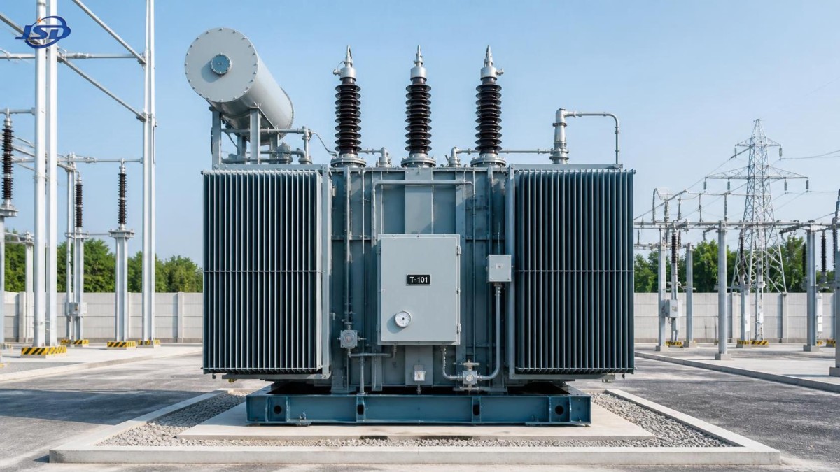
Outdoor transformers need more than a weatherproof finish. Confirm clearances for live parts, lifting routes, maintenance access, cable approach, noise boundaries, and protection equipment. Radiators must have room to reject heat; placing them close to walls or behind solid barriers can undermine the assumed cooling performance. For substations in constrained urban or industrial plots, it is worth reviewing the physical arrangement with the manufacturer before the foundation and cable trenches are finalized.
Indoor installations require even more discipline. Room ventilation, fire strategy, door dimensions, floor loading, rail or crane access, and routes for replacement are practical constraints that cannot be repaired easily after construction. If a transformer must pass through a narrow opening, the transport dimensions with radiators, bushings, and accessories removed should be checked—not simply the overall dimensions shown on an early datasheet.
Noise should be evaluated where the transformer is close to offices, residential areas, hospitals, or control rooms. Core noise is influenced by design and supply conditions, while fans and pumps, where fitted, introduce additional sound sources. A low-noise requirement should be stated clearly at inquiry stage, along with the measurement condition expected by the project. Leaving it until factory testing invites disagreement because “quiet” is not an engineering criterion.
Special rectifier and industrial duties need a different conversation
When the transformer feeds a rectifier system, the evaluation should go beyond conventional distribution-transformer data. Rectifier loads can demand a customized low-voltage output, suitable phase displacement, robust thermal performance under harmonic current, and electrical isolation between the supply network and the conversion equipment. Metallurgy, electrolysis, electroplating, chemical processing, mining, rail systems, and industrial power-electronic installations commonly raise these questions.
For this type of duty, an Isolation and Rectifier Special Transformer can be assessed as a purpose-built option rather than treated as a standard utility transformer with a custom terminal voltage. Available configurations may cover 50 kVA to 5000 kVA, with 6 kV, 10 kV, 20 kV, or 35 kV high-voltage options and customized low-voltage arrangements. Three-phase Dyn11 or Yyn0 connection groups, 50 Hz or 60 Hz operation, indoor or outdoor installation, and ONAN or AN cooling can be selected according to the actual rectifier system design. The stated IEC 60076 basis is useful, but the buyer should still define harmonic duty, insulation coordination, load cycle, and required tests in the technical schedule.
Copper winding material is often specified for demanding industrial service because conductivity and thermal behavior directly affect losses and temperature rise. Still, winding material alone is not a quality verdict. The evaluator should look at conductor sizing, insulation structure, clamping, short-circuit withstand capability, cooling paths, and the manufacturer’s ability to manage the complete design and manufacturing process.
Turn the specification into an evaluation checklist
A useful transformer inquiry package should describe what the unit must endure, not merely what it must be called. Before comparing offers, confirm the following points with the project team:
- Normal, peak, emergency, and future load conditions, including load duration and harmonic content.
- System voltage, frequency, insulation level, tap requirement, vector group, grounding method, and fault level.
- Ambient temperature range, altitude, solar exposure, pollution severity, humidity, and corrosive conditions.
- Indoor or outdoor location, available footprint, ventilation, cable entry, lifting route, maintenance access, and noise limits.
- Insulating-fluid preference, fire protection philosophy, containment arrangement, and local approval requirements.
- Required accessories, monitoring, protection interfaces, routine tests, type-test evidence where applicable, and documentation format.
The bid comparison should then distinguish between compliant design choices and vague assumptions. Two quotations with the same power rating can differ substantially in loss values, temperature-rise assumptions, accessory quality, protection provisions, transport arrangement, and suitability for the stated site. A low initial price may omit exactly the details that later become costly: an inadequate marshalling box, unsuitable bushings, limited monitoring, insufficient coatings, or a cooling layout that does not match the ambient condition.
A practical final review before release
Before issuing a purchase order, hold one joint review involving electrical design, civil works, operations, protection, and the transformer supplier. Verify terminal positions against cable routes, total mass against the foundation, clearances against the substation layout, and accessory locations against maintenance access. Check whether the specified ratings apply at the project ambient temperature and altitude, rather than under generic reference conditions. For rectifier or non-linear loads, confirm that the manufacturer has received the relevant waveform and duty information.
Manufacturers with dedicated power-equipment engineering and controlled production processes can help translate these inputs into a workable design. Jinshida Electric Power Technology Co., Ltd. focuses on transmission and distribution equipment for grid, industrial, new-energy, and infrastructure applications, with attention to stable operation, manufacturing quality, and technical support. The most productive supplier relationship, however, begins with a complete operating picture. Give the design team the hard conditions early; that is usually where transformer reliability is won or lost.

Get a Quote
Regardless of whether you require general advice or specific support, we are happy to help you.
Send Us Your Inquiry Today

Jinshida Electric remains committed to contributing to global energy development through professional manufacturing and superior service.