





Choosing a 33 kV transformer for utility-connected solar plants
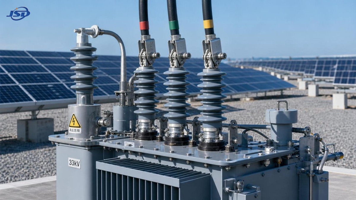
Selecting a 33 kV transformer for a utility-connected solar plant is not mainly a question of choosing the largest kVA rating at the lowest purchase price. The right unit must match the utility interconnection requirements, the plant’s real operating profile, inverter behavior, protection philosophy, and environmental exposure. A transformer that looks acceptable on a single-line diagram can still create commissioning delays, voltage-control problems, or unnecessary energy losses once the plant is energized.
For a solar project, the transformer sits between a fast-changing generation source and a grid that expects predictable electrical behavior. That is why selection should start with the grid connection agreement and protection study, then move outward to capacity, vector group, impedance, cooling, insulation, monitoring, and supplier support.
Start with the grid connection, not the transformer catalogue
The first document to review is the utility’s interconnection specification. A 33 kV transformer may be part of a collector system, a step-up arrangement from low-voltage inverter blocks, or a transformer feeding a 33 kV export feeder. These are different duties, even when the nominal voltage is the same.
Confirm the required nominal voltage, permitted voltage range, frequency, earthing arrangement, short-circuit level, reactive power requirements, and protection interface. Utilities may also specify transformer vector groups, neutral grounding methods, tap-changer requirements, surge arresters, metering arrangements, and fault ride-through expectations for the overall plant.
A common mistake is to assume that “33 kV” fully defines the high-voltage side. It does not. A nominal 33 kV network may have its own allowable operating band, insulation coordination rules, and switching surge considerations. The transformer’s highest voltage for equipment, basic insulation level, bushings, arresters, and cable terminations need to suit the actual network design, not just the voltage printed on a preliminary drawing.
Before requesting quotations, freeze these points as far as possible:
- Point of common coupling voltage and utility-required voltage tolerance.
- Maximum and minimum grid voltage expected at the transformer terminals.
- Solar plant export capacity, inverter apparent-power rating, and reactive-power operating range.
- Required vector group and neutral treatment.
- Calculated fault level at the 33 kV bus and required transformer short-circuit withstand.
- Applicable standards, including the edition and any utility-specific deviations.
- Site altitude, ambient temperature, pollution level, seismic requirement, and installation layout.
This information makes supplier proposals comparable. Without it, two quotations with the same MVA rating may represent materially different electrical designs.
Size the 33 kV transformer for operating duty, not DC module capacity
Solar plants are often discussed in MWp on the DC side, while transformers are rated in kVA or MVA on the AC side. Treating those figures as interchangeable causes early sizing errors. The transformer must carry the maximum expected AC apparent power, including the reactive power that may be required by the grid operator.
For example, a plant may export active power near its AC nameplate rating while also being asked to operate at a specified power factor or provide voltage support. Reactive power consumes transformer capacity even though it does not add to energy delivered in kWh. Inverter clipping, curtailment rules, battery integration, and future expansion can also alter the real loading profile.
A practical approach is to calculate the highest continuous apparent power under the required grid-support mode, then assess whether a margin is justified by ambient conditions, solar irradiance profile, harmonic heating, and planned expansion. Oversizing is not automatically prudent. An oversized transformer has higher capital cost and may carry greater no-load losses for decades. Undersizing, however, can limit export, increase thermal stress, and make compliance with reactive-power requests difficult.
The design decision should be documented with a load schedule, not based on an informal rule of thumb. Ask the electrical designer to show the assumed active power, reactive power, power factor, maximum inverter output, and expected transformer loading at the site’s design ambient temperature.
Voltage ratio and tap range deserve more attention than they usually receive
In a utility-connected solar plant, voltage regulation is an operating issue, not a paperwork detail. Cable voltage drop across the collection network, grid voltage changes, inverter voltage limits, and reactive-power dispatch all affect the voltage seen by equipment. A suitable ratio and tap arrangement can provide useful operating headroom; the wrong arrangement can leave the plant repeatedly operating near inverter limits.
For many solar applications, an off-circuit tap changer is adequate because the transformer ratio is set during commissioning or planned outages. An on-load tap changer may be appropriate where grid voltage varies substantially, where the transformer serves a broader distribution duty, or where the utility explicitly requires active voltage regulation. It adds complexity, maintenance needs, control integration, and cost, so it should not be specified by default.
Do not select a tap range simply because it is standard in a supplier’s catalogue. Confirm which winding is tapped, the number and size of tap steps, the preferred nominal tap, and whether the proposed range actually addresses the calculated voltage variation. This review should include the inverter supplier, cable designer, and grid studies engineer.
Impedance, vector group, and earthing are protection decisions
Transformer impedance influences fault current, voltage drop, parallel operation, and the behavior of protection devices. A lower impedance can improve voltage regulation but may increase fault duty. A higher impedance can limit fault current but may create a larger voltage drop under load. There is no universal “best” impedance percentage for solar plants.
The correct value comes from coordination studies. It must work with the 33 kV switchgear rating, feeder protection, inverter contribution to fault current, cable impedance, and the utility’s protection settings. Inverter-based generation behaves differently from synchronous generation, so protection studies should use realistic inverter fault-current characteristics supplied by the inverter manufacturer.
Vector group selection is equally important. It affects phase displacement, zero-sequence behavior, harmonic paths, and grounding options. A delta winding can block zero-sequence currents from passing between sides, while a grounded star winding may be required to establish a reference for the medium-voltage system. The final choice must align with the network earthing philosophy and relay scheme. Copying the vector group from another project can be risky when the grid arrangement is different.
Ask for a coordinated package: transformer vector group, neutral grounding equipment, surge protection, cable screen bonding approach, and protection settings should be reviewed together. Treating them as separate procurement items often creates late design changes.
Losses matter because solar plants have long operating lives
Transformer losses are usually divided into no-load loss and load loss. No-load loss exists whenever the transformer is energized, including at night. Load loss rises with current and is more significant when the transformer operates heavily. Solar plants have a distinctive profile: daytime loading can be high, but the transformer remains energized through low-generation and non-generating hours.
That makes lifecycle evaluation more useful than comparing only the initial price. A lower-loss design can be commercially sensible when energy prices, operating hours, and loss capitalization assumptions support the additional cost. The calculation needs transparent assumptions. Electricity value, plant availability, local energy rules, and expected operating profile vary by project, so no generic payback figure should be accepted without checking the underlying model.
For low-voltage auxiliary distribution within a photovoltaic facility, a product such as the 30kV/0.4kV Oil-Immersed Power Distribution Transformer may be relevant where the site design calls for a 30 kV-to-0.4 kV supply. Its stated application range includes photovoltaic power plants, and its listed ratings from 500 kVA to 1600 kVA can suit local distribution duties. It should not be substituted for a 33 kV connection transformer unless the project voltage architecture and utility requirements specifically support that arrangement.
That distinction matters. A robust auxiliary transformer does not automatically solve the main grid interconnection duty. Keep the equipment roles clear in the technical schedule.
Choose the construction around the site, not preference alone
Oil-immersed transformers remain a common choice for outdoor solar sites because they offer effective cooling and are available across a broad power range. They need proper oil containment, fire-risk assessment, access for inspection, and an environmental plan for leaks or end-of-life handling. Where fire restrictions, indoor placement, or sensitive locations govern the design, dry-type construction may be considered, but it has its own thermal and cost implications.
Ambient temperature and altitude cannot be treated as minor details. High ambient temperatures reduce cooling margin. Higher elevations reduce air density and can affect insulation clearances and cooling performance. Coastal, desert, agricultural, and industrial locations bring different contamination and corrosion risks. The transformer enclosure, bushings, radiators, cable boxes, paint system, and terminal protection should all reflect the actual site conditions.
For remote plants, monitoring is often worth more than a marginal saving in purchase cost. At minimum, specify the temperature indications, alarms, trips, oil level indication where applicable, pressure relief arrangement, and interface points required by the plant SCADA system. Larger or higher-criticality units may justify dissolved gas monitoring, bushing monitoring, or other condition-monitoring measures, but the selected system should match the maintenance strategy. Installing complex sensors without a clear response process does not improve reliability.
What a technically usable transformer specification should contain
A supplier cannot provide a meaningful final design from only “33 kV, solar project, 10 MVA.” A usable specification should define electrical duty and site duty in the same document.
Include rated power and cooling stage, voltage ratio, frequency, vector group, impedance tolerance, tap arrangement, winding material requirements if applicable, insulation level, losses, temperature-rise limits, short-circuit withstand, terminal arrangement, bushing creepage distance, neutral details, accessories, painting system, applicable standard, routine tests, type-test expectations, factory acceptance test requirements, documentation, packing, and spare parts.
It is also sensible to identify the contractual boundary. Clarify whether the supplier provides only the transformer or also surge arresters, neutral grounding equipment, marshalling kiosk, cable boxes, monitoring devices, transport supervision, oil filling, site testing, and commissioning support. Ambiguous boundaries are a frequent source of schedule disputes.
Jinshida Electric Power Technology Co., Ltd. focuses on transmission and distribution equipment for grid, industrial, infrastructure, and new-energy applications. For a solar transformer package, the useful question is not simply whether a manufacturer can build the unit, but whether its engineering team can review the grid data, site conditions, test requirements, and documentation package before production. A rigorous quality process is most valuable when it results in clear approved drawings, traceable testing, and equipment that matches the approved specification.
Do not accept “IEC compliant” as the whole answer
IEC 60076 is widely used for power transformer design and testing, but the phrase “IEC compliant” alone is too broad for procurement. Confirm the exact standard edition, applicable clauses, loss requirements, insulation requirements, test scope, and the utility’s additional conditions. If local regulations or the grid operator requires ANSI/IEEE, EN, GOST, or another framework, define that requirement before award.
Routine tests should be agreed in the purchase specification. Depending on the project and transformer rating, the buyer may require witnessed factory acceptance testing, ratio and vector-group verification, winding resistance measurements, impedance and load-loss testing, no-load loss and current measurements, dielectric tests, and accessory functional checks. Any special test should be identified early, because it may influence design, factory scheduling, and cost.
A good factory acceptance test is not a ceremonial visit. It is the last practical opportunity to compare the completed unit against approved drawings, nameplate data, test records, accessory lists, terminal markings, and transport requirements before shipment.
Questions that prevent late surprises
Should the transformer rating include future solar expansion?
Only when expansion is credible and the rest of the electrical system can support it. Check feeder capacity, switchgear ratings, protection settings, land use, export agreement limits, and inverter plans. Buying extra transformer capacity alone does not create usable future export capacity.
Is a higher overload capability enough to reduce the transformer rating?
No. Short-term overload capability is conditional on temperature, prior loading, cooling, and manufacturer limits. It may help during exceptional events, but it should not replace the continuous-duty rating required by the plant’s export and reactive-power obligations.
Can a 30 kV transformer be used on a 33 kV system?
Not as an assumption. Nominal voltage, highest voltage for equipment, insulation level, tap range, and utility approval must all be checked. A 30 kV product may suit a 30 kV collector or auxiliary network, but it is not automatically suitable for a 33 kV interconnection.
What is the most common procurement mistake?
Issuing a vague specification and comparing bids only by price and MVA rating. Differences in losses, impedance, insulation level, accessories, test scope, and delivery responsibility can make the lower quotation the more expensive choice after commissioning.
Near the end of the selection process, review the 33 kV transformer as part of the complete electrical system: utility grid, inverters, collector cables, switchgear, protection relays, grounding, and operations plan. The best choice is the unit whose documented design fits that system and whose supplier can demonstrate compliance through drawings, tests, and support. That is the decision that protects schedule, energy delivery, and long-term plant availability.

Get a Quote
Regardless of whether you require general advice or specific support, we are happy to help you.
Send Us Your Inquiry Today

Jinshida Electric remains committed to contributing to global energy development through professional manufacturing and superior service.