





How to Monitor an Oil Immersed Transformer for Temperature and Insulation Problems
How to Monitor an Oil Immersed Transformer for Temperature and Insulation Problems
Reliable temperature and insulation monitoring is one of the most practical ways to extend the service life of an oil immersed transformer. Most serious transformer failures do not begin with a dramatic event. They often develop through a gradual rise in temperature, declining oil quality, moisture entering the insulation system, blocked cooling paths, or a small electrical defect that becomes active under load.
For operators, the goal is not merely to record readings. It is to understand what has changed, why it has changed, and whether the condition requires observation, maintenance planning, load adjustment, or an immediate response. A single high temperature reading can be influenced by ambient conditions or temporary loading. A persistent trend, especially when it disagrees with expected operating behavior, deserves much more attention.
An effective monitoring program combines routine visual checks, operating data, oil testing, and disciplined comparison with the transformer’s nameplate, design documents, and historical records. This approach helps operators detect overheating and insulation deterioration before they lead to an unexpected outage.
Why Temperature and Insulation Must Be Read Together
Temperature and insulation condition are closely connected. Transformer oil transfers heat away from the windings and core while also providing dielectric insulation. The solid insulation, generally paper or pressboard in an oil-filled unit, supports the long-term electrical integrity of the winding system. Excess heat accelerates insulation aging; moisture weakens dielectric strength and can make overheating more damaging.
This is why a normal oil level alone does not prove that an oil immersed transformer is healthy. Likewise, a temperature alarm does not automatically mean the winding has failed. The practical question is whether the measured temperature is reasonable for the load, ambient temperature, cooling mode, and recent operating history. If it is not, operators should investigate the cooling system and insulation indicators rather than simply resetting an alarm.
The most useful records show relationships: load against top-oil temperature, ambient temperature against cooling response, and oil-test results against previous samples. These comparisons reveal deterioration far more clearly than isolated readings collected during an inspection.
Start with the Temperatures That Tell a Useful Story
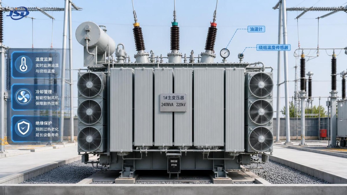
Most installations have at least a top-oil temperature indicator. Larger or more critical units may also use winding temperature indicators, resistance temperature detectors, fiber-optic sensors, remote telemetry, or supervisory control systems. Each measurement has a different purpose, and confusing them can lead to poor decisions.
Alarm and trip values should always follow the manufacturer’s instructions and the site’s approved protection settings. Do not adopt a temperature limit from another transformer simply because the equipment appears similar. Cooling class, insulation design, sensor location, tap position, ambient environment, and loading pattern can all affect the correct interpretation.
A common warning sign is a temperature that rises faster than usual at a comparable load. Another is high top-oil temperature with fans running but little apparent cooling benefit. Before assuming an internal fault, check whether radiator valves are open, fans are rotating in the intended direction, airflow is obstructed, pumps are operating where fitted, and cooling controls are actually responding to the temperature signal.
Inspect the Cooling System Before Blaming the Transformer Core
Cooling defects are among the more accessible causes of overheating, yet they are sometimes overlooked because the transformer continues to carry load. Inspect radiators for contamination, damaged fins, oil leaks, corrosion, and restricted airflow. In dusty industrial areas, on construction sites, or near agricultural processing operations, radiator surfaces can lose heat-transfer performance gradually. A fan may also sound as if it is running while delivering inadequate airflow.
For units with forced cooling, verify automatic and manual fan control, motor condition, power supply, contactors, thermostatic switches, and alarm circuits. Where oil pumps are used, investigate abnormal vibration, noise, or reduced flow indications. The transformer should be evaluated under actual operating conditions; a cooler that appears normal during low load may not provide sufficient margin during peak demand.
Thermal imaging can be useful during an energized inspection when performed by qualified personnel under site safety procedures. It can help identify unusually warm cable terminations, bushings, connections, cooling components, and localized hot areas. It does not replace electrical testing, but it can direct attention to parts that need a closer inspection during the next safe outage.
Use Oil Condition as an Early Insulation Warning
Oil sampling gives operators a view into conditions that cannot be seen from outside the tank. The value of the sample depends on correct collection, clear labeling, and trend comparison. A contaminated bottle, a sample taken from the wrong point, or incomplete operating information can make laboratory results difficult to interpret.
The testing program commonly considers moisture, dielectric breakdown voltage, acidity, interfacial tension, color or appearance, and dissolved gas analysis where appropriate. These tests answer different questions. Moisture can reduce dielectric performance and migrate between oil and paper depending on temperature. Acidity and related oil-condition indicators may point to oxidation and aging. Dissolved gases can provide clues about thermal faults, electrical discharge, or arcing, but gas results must be reviewed as a pattern rather than treated as a simple pass-or-fail number.
If dissolved gas results change materially from earlier samples, or if a new gas pattern appears after a load event, switching incident, or overheating alarm, escalation is sensible. The next step may be repeat sampling, a review by a qualified diagnostic specialist, additional electrical tests during outage, or closer online monitoring. The appropriate response depends on the rate of change, the gases present, the unit’s criticality, and its operating history.
Moisture ingress is often a maintenance problem before it becomes an electrical problem
Water can enter through damaged gaskets, leaking valves, deteriorated seals, poorly maintained breathers, or ineffective conservator protection. A silica-gel breather that has changed color should not be treated as a cosmetic issue. It may indicate that the drying medium has reached the end of its useful condition. Also inspect the oil seal, breather piping, conservator bladder or diaphragm arrangement where installed, and the area around the tank cover.
Visible water, cloudy oil, persistent condensation around fittings, or unexplained oil-level behavior should be acted on promptly. However, moisture is not always obvious. Laboratory testing and historical comparison are needed to assess whether water is increasing in the oil or whether the paper insulation may be at risk. Avoid opening the transformer unnecessarily in humid conditions, since maintenance itself can introduce moisture if controls are weak.
Do Not Ignore External Insulation Clues
Bushings, cable boxes, arresters, and external terminations are part of the insulation system seen by the operator every day. Check porcelain or composite surfaces for cracking, tracking, contamination, oil seepage, loose hardware, and signs of flashover. In coastal, polluted, or high-humidity environments, surface contamination can become a serious operational issue even when the oil inside the main tank remains acceptable.
Pay attention to unusual sound as well. A steady transformer hum is expected; new buzzing, crackling, intermittent discharge noise, or a change in vibration should be recorded and investigated. The same applies to repeated pressure-relief operation, sudden oil-level movement, or protection alarms that clear without an obvious external cause. These are not conditions to normalize simply because the transformer remains energized.
Build a Routine That Produces Decisions, Not Just Logs
A useful operating routine separates frequent checks from periodic condition assessment. During normal rounds, record load, top-oil temperature, ambient condition, oil level, pressure indication where applicable, cooling equipment status, leaks, and alarms. Add comments when conditions are unusual: a heat wave, a planned overload, a fan control repair, or a recent switching event. Those notes often explain later trends.
At planned intervals, review oil-test history, protection records, infrared inspection findings, bushing condition, grounding connections, and cooling-system maintenance. Critical transformers may justify continuous temperature and gas monitoring, while smaller distribution units may be managed effectively through disciplined manual inspection and periodic testing. The decision should reflect outage consequences, load importance, access conditions, and the cost of losing the unit—not a one-size-fits-all maintenance rule.
When a reading is abnormal, document the time, loading, ambient temperature, cooling stage, alarm state, and any visible condition. Then ask three practical questions: Is the reading credible? Is it changing? Is there a safe operating action available now? Reducing load, restoring cooling, tightening a verified external connection during a planned isolation, or arranging urgent oil analysis may be appropriate. Internal inspection should only be considered with qualified engineering guidance and proper isolation procedures.
When the Installation Calls for a Different Insulation Approach
Monitoring an oil-filled unit carefully remains essential, but some projects have constraints that change the equipment decision. Indoor substations, commercial buildings, public facilities, renewable-energy sites, and locations with stricter fire-performance expectations may require evaluation of dry-type alternatives. This is not a universal replacement decision: voltage level, installation space, load profile, ventilation, protection requirements, and local codes all need to be reviewed.
For 20 kV distribution applications, the 20kV Three-Phase Cast Resin Dry-Type Distribution Transformer is designed around air or solid resin insulation rather than liquid coolant and includes temperature protection and control capability. The SCB10-12 range covers capacities from 50 kVA to 5000 kVA, with common listed sizes from 200 kVA to 2500 kVA. Its stated 20 kV input and 0.4 kV or 0.415 kV output options may be relevant where a project needs a dry-type distribution arrangement, but final selection must still match the network, enclosure, ambient conditions, and applicable standards.
Jinshida Electric Power Technology Co., Ltd. works across the research, manufacturing, and application of transmission and distribution equipment for grid, industrial, new-energy, and infrastructure projects. In practice, reliable operation starts long before commissioning: design verification, manufacturing process control, clear technical documentation, and an achievable inspection plan all affect how easily operators can manage equipment throughout its service life.
A Practical Escalation Point
An oil immersed transformer should be reviewed without delay when temperature rises unexpectedly at normal load, cooling equipment cannot maintain the expected response, oil leakage is active, a breather or seal condition suggests moisture exposure, protective devices operate, or oil-test trends indicate a developing insulation concern. Waiting for a second alarm can turn a manageable maintenance issue into a forced outage.
The strongest maintenance decisions come from trends supported by field observations. Keep the records consistent, compare like-for-like operating conditions, and involve qualified transformer specialists when evidence points to an internal thermal or dielectric problem. That discipline gives operators the information needed to protect the asset, plan work safely, and avoid making major decisions based on one isolated number.

Get a Quote
Regardless of whether you require general advice or specific support, we are happy to help you.
Send Us Your Inquiry Today

Jinshida Electric remains committed to contributing to global energy development through professional manufacturing and superior service.