





Which Tests and Standards Should an Oil Immersed Transformer Pass Before Acceptance?
It is a familiar acceptance-day problem: the oil immersed transformer is already on site, the civil work is nearly complete, and the installation schedule is under pressure. The supplier has provided a test folder, but the documents do not immediately answer the questions that matter most: Were the correct tests performed? Do the recorded values match the approved design? Was the transformer damaged during transport? Can it be energized without creating an avoidable insulation, thermal, or protection risk?
A transformer can look intact while carrying hidden defects. A loose internal connection, moisture-contaminated oil, incorrect tap position, inadequate dielectric strength, or transport-related winding movement may not be visible during a walk-around inspection. If these issues are missed, the consequences can include failed energization, unexpected relay operation, oil leakage, overheating, and difficult fault investigations after the unit has entered service. A sound acceptance process therefore combines factory documentation review, physical inspection, site verification, and a clear understanding of which standards govern each test.
Start with the contract, not the test report
Before reviewing measured values, confirm the technical basis against which the oil immersed transformer was manufactured. A test result is only useful when it is compared with an agreed requirement. The purchase specification, approved drawings, data sheet, nameplate schedule, and inspection-and-test plan should identify the applicable standard edition, rated power, voltage ratio, vector group, impedance, cooling class, insulation level, tap range, terminal arrangement, accessories, and required tests.
For many international projects, the core reference is the IEC 60076 series. Depending on the transformer design and duty, the relevant parts commonly include IEC 60076-1 for general requirements, IEC 60076-2 for temperature rise, IEC 60076-3 for insulation levels and dielectric tests, IEC 60076-5 for short-circuit withstand capability, IEC 60076-7 for loading guidance, and IEC 60076-10 for sound-level determination. Projects using North American practice may instead specify IEEE C57 standards, such as IEEE C57.12.00 and IEEE C57.12.90. National requirements, utility specifications, or local grid codes can add further obligations.
Do not assume that every test listed in a standard is automatically required for every unit. Standards distinguish among routine tests, type tests, special tests, and tests required by agreement. The acceptance team should identify which category applies before treating a missing report as either acceptable or nonconforming.
Separate routine tests from evidence of design capability
Routine tests are performed on each manufactured transformer and are the foundation of factory acceptance. They verify that the individual unit conforms to its specified electrical characteristics and has passed essential dielectric checks. Type tests demonstrate characteristics of a representative design, while special tests are requested where the application, purchaser specification, or risk profile requires extra confirmation.
A common mistake is accepting a type-test certificate as a substitute for a unit-specific routine test. For example, a prior temperature-rise report may support the design, but it does not prove that the particular delivered unit has the correct ratio, impedance, winding resistance, oil condition, or dielectric test performance. Conversely, requesting a full temperature-rise test on every standard distribution transformer may be unnecessary unless the contract explicitly requires it.
The practical question is not “Does the supplier have certificates?” It is “Does the supplied transformer have traceable evidence that every contractual and applicable acceptance requirement was met?”
The factory test records that deserve close attention
Routine-test records should be complete, legible, dated, and linked to the transformer serial number. They should state the test method, relevant standard, measured values, instrument details where required, and final result. A simple “passed” stamp without data is rarely sufficient for a critical item.
Ratio, polarity, vector group, and tap verification
Transformer ratio testing confirms that the actual voltage transformation corresponds to the nameplate and approved design. Measurements should be reviewed at every available tap position, not only at the nominal tap. Incorrect ratio or tap connections can create parallel-operation problems, voltage regulation errors, or commissioning delays.
For three-phase units, vector group and phase displacement verification are equally important. The reported vector group must match the system design and protection scheme. A transformer with an incorrect phase relationship may be impossible to parallel with existing equipment and can cause serious errors in metering or protection connections.
Winding resistance measurement
Winding resistance testing helps reveal poor joints, damaged conductors, tap-changer contact problems, and winding connection errors. Values should be recorded for each phase and tap as applicable. Because copper and aluminium resistance changes with temperature, comparisons should use corrected values or clearly documented test temperatures.
Large phase deviations, unexplained variation between adjacent tap positions, or values that differ materially from factory reference data require investigation. The right response is not to set an arbitrary universal percentage limit; conductor arrangement, winding design, test temperature, and tap-changer configuration all affect interpretation. Compare like with like, and require the manufacturer to explain any abnormal pattern.
Impedance voltage and load-loss test
Short-circuit impedance affects fault-current calculations, voltage regulation, and the ability to operate transformers in parallel. The measured impedance must be within the tolerance stated by the governing specification or standard. Load-loss results are typically obtained during this test and should also be compared with guaranteed values under the stated reference conditions.
Unexpected impedance variation is not merely an efficiency issue. It can indicate a departure from the specified winding geometry or may create coordination difficulties in the downstream system. Verify the rated frequency, tap position, temperature correction basis, and test connection before drawing conclusions from a discrepancy.
No-load loss and excitation current
No-load loss and excitation current testing provides useful information about the magnetic core and energization behavior. The values should be reviewed against the guaranteed limits in the order specification. A higher-than-expected no-load loss may point to core-material, assembly, or excitation concerns, while unusual phase patterns in excitation current may warrant further examination.
These results should not be judged in isolation. Test voltage waveform, voltage level, instrument accuracy, and the specified tolerance framework matter. The acceptance record should make the comparison transparent rather than presenting only a single final number.
Dielectric tests: the point at which shortcuts become dangerous
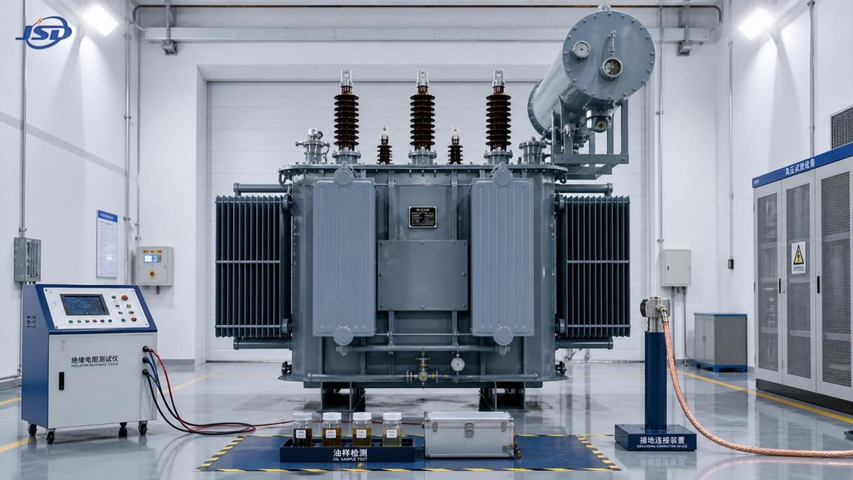
Dielectric tests verify whether the insulation system can withstand stresses expected in service and specified test levels. IEC 60076-3 is a key reference for insulation levels and dielectric testing. The exact test sequence depends on transformer class, insulation design, terminal configuration, and purchaser requirements.
Typical factory dielectric tests may include separate-source applied-voltage tests, induced-voltage withstand tests, and where specified, lightning impulse tests. Applied-voltage tests examine insulation between windings and earth or other designated parts. Induced-voltage tests impose elevated internal voltage to assess turn-to-turn, layer-to-layer, and phase-to-phase insulation. Impulse tests examine the ability of the insulation system to withstand fast-front surge conditions associated with lightning or switching events.
For units where impulse testing is specified, the report should identify the terminal tested, wave records where applicable, polarity, test level, and assessment of the response. A statement that an impulse test was “completed” is weaker than traceable evidence showing that the required procedure was followed. Any chopped-wave requirement, neutral treatment, or reduced-level sequence should align with the approved specification.
It is also important to distinguish between factory dielectric tests and simplified site tests. Field insulation-resistance readings can help identify moisture or contamination after shipment, but they do not replace the complete factory dielectric test program. Do not attempt to repeat high-voltage factory tests in the field without an approved procedure, competent personnel, suitable equipment, and a clear technical reason.
Oil, tank, and accessory checks often decide site readiness
The electrical test file is only one part of acceptance. An oil immersed transformer depends on the condition of its insulating liquid, sealing system, cooling equipment, and protective accessories. These items deserve a structured review before energization.
For mineral insulating oil, the specification may reference IEC 60296 for unused oil and IEC 60422 for supervision and maintenance guidance. Common oil tests include dielectric breakdown voltage, moisture content, acidity, interfacial tension, dissipation factor, and dissolved gas analysis where appropriate. IEC 60156 is commonly used for determination of breakdown voltage, while IEC 60567 addresses sampling of gases and oil for free and dissolved gas analysis.
The required oil tests depend on whether the transformer is supplied oil-filled, shipped under nitrogen, or filled on site. If the unit was transported with oil, inspect the shipping condition, oil level, pressure records if applicable, seals, valves, radiators, and conservator arrangement. If it was shipped dry or under gas pressure, verify the preservation procedure, gas pressure history, dew-point controls where specified, and the approved filling and vacuum process.
Pay close attention to accessory operation. Check that oil level indicators, winding and oil temperature indicators, pressure-relief devices, Buchholz relays where fitted, cooling fans, pumps, gauges, alarm contacts, trip contacts, marshalling-box wiring, and terminal labels correspond to the approved drawings. A relay may be mechanically installed yet electrically miswired, so functional checks should include contact verification against the protection scheme.
A practical acceptance path from factory release to energization
Acceptance is more reliable when it is treated as a controlled sequence rather than a final signature on a delivery note.
- Freeze the reference documents. Use the approved technical specification, approved drawings, and contractual test schedule. Record deviations formally rather than resolving them through informal email comments.
- Review the factory dossier before dispatch. Confirm routine-test reports, applicable type or special-test evidence, nameplate details, material certificates where requested, instruction manuals, packing information, and nonconformance closures.
- Inspect on arrival. Look for impact damage, paint damage, oil stains, loose fittings, broken bushings, damaged radiators, compromised seals, missing earth connections, and signs that shipping restraints were disturbed.
- Verify identity and configuration. Match the serial number, rating plate, vector group, impedance, tap range, cooling designation, terminal markings, and accessory list to the approved documentation.
- Carry out site tests appropriate to the condition and project procedure. These may include insulation resistance, winding resistance, ratio and vector-group checks, tap-changer functional checks, oil sampling, and control-circuit checks. The scope should reflect voltage class, storage duration, transport condition, and contractual requirements.
- Resolve anomalies before energization. A damaged gauge, inconsistent test result, low oil level, unexplained pressure loss, or mismatch in documentation should trigger a documented technical review. Avoid accepting a deviation solely because the schedule is tight.
When additional tests are justified
Some applications call for more than standard routine testing. Large power transformers, units intended for critical infrastructure, transformers exposed to severe environmental conditions, or equipment designed for parallel operation may justify special testing. Possible examples include sound-level measurement under IEC 60076-10, zero-sequence impedance measurement, short-circuit withstand evidence, frequency-response analysis, dissolved gas baseline testing, or enhanced partial-discharge assessment when specified for the design.
The decision should be risk-based. Consider fault level, voltage class, service continuity requirements, transport route, storage duration, ambient conditions, proximity to occupied buildings, and the consequences of a failed energization. Testing should answer a real technical question; it should not become a generic list detached from the transformer’s duty.
Where indoor installation, fire performance, and elimination of liquid-insulation concerns are dominant project factors, the selection process may lead to a dry-type alternative rather than an oil-filled unit. For example, a 11kV Three-Phase Cast Resin Dry-Type Distribution Transformer is intended for 11 kV distribution applications and uses cast-resin insulation rather than insulating oil. That does not make its acceptance process identical: the applicable tests, cooling arrangement, and installation considerations must still be checked against its own specification and standards.
Records that should remain with the asset
Once acceptance is complete, retain the final document pack with the transformer’s operating records. At minimum, it should include approved drawings, factory and site test reports, oil test results, shipping and storage records, commissioning check sheets, accessory settings, protection-interface information, manuals, and documented deviations. These records become valuable when comparing future oil samples, investigating a protection event, assessing loading, or planning maintenance.
The safest acceptance decision is rarely based on one impressive test certificate. It comes from a consistent chain of evidence: the correct standard was selected, the required tests were performed on the actual unit, measured values were checked against the approved specification, the transformer arrived in acceptable condition, and site verification found no unresolved concern. When that chain is complete, energization is a controlled engineering decision rather than a leap of faith.
Hot News
- 00
0000-00
How U.S. DOE efficiency rules affect distribution transformer manufacturers - 00
0000-00
How american type pad mounted transformer seismic qualification affects installation in California utility grids? - 00
0000-00
Do european compact substation transformer EMC compliance tests include conducted emissions up to 30MHz?
0000-00
Contact Us

Get a Quote
Regardless of whether you require general advice or specific support, we are happy to help you.
Send Us Your Inquiry Today

Jinshida Electric remains committed to contributing to global energy development through professional manufacturing and superior service.