





Factory Acceptance Tests for Copper-Winding Distribution Transformers: A Buyer's Checklist
A factory acceptance test should be treated as a release decision, not a ceremonial witness test. Before a copper winding distribution transformer leaves the factory, the buyer needs evidence that the unit was built to the approved design, that its electrical characteristics match the nameplate and purchase specification, and that no manufacturing defect has been hidden by a clean paint finish or a passing routine test alone.
The most effective approach is to agree on the inspection and test plan before production is complete. That plan should identify the applicable technical standard, the contractual requirements, test methods, acceptance values where applicable, documents to be submitted, witness points, and the action required for a failed or repeated test. A signed test report without this context is not enough.
Start with the approved technical baseline
Every acceptance decision should be traced back to a controlled set of documents: the purchase order, approved drawings, guaranteed technical data, nameplate schedule, and any project-specific requirements. The factory may build several similar transformers with different voltage ratios, vector groups, impedance values, tap arrangements, enclosure ratings, or terminal layouts. A unit can pass its electrical tests and still be wrong for the installation if these details are not checked first.
Confirm the following before moving to electrical testing:
- Rated power, primary and secondary voltage, frequency, phase arrangement, and vector group.
- Specified cooling method, insulation class, temperature-rise basis, and installation environment.
- Tap changer type, tap positions, operating mechanism, and required locking or indication features.
- Short-circuit impedance, loss guarantees when stated in the contract, and required accessories.
- Terminal markings, neutral arrangement, earthing points, cable box or bushing configuration, and clearances.
- Nameplate language, serial number, mass, lifting instructions, oil data for liquid-filled units, and warning labels.
This first comparison prevents a common acceptance error: approving a transformer because the test report appears complete, while the physical unit does not match the approved application design.
Inspect the copper winding work before relying on test values
Copper conductors are often selected for their conductivity, mechanical strength, and dependable performance under thermal cycling. However, the value of a copper winding distribution transformer depends on execution, not conductor material alone. The factory inspection should establish that the winding assembly is adequately supported, insulated, connected, and prepared to withstand service stresses.
Where the construction is visible during the inspection stage, examine winding leads, insulation barriers, clamping structures, tap leads, and connections for signs of poor workmanship. Look for sharp edges at conductor bends, damaged insulation paper or pressboard, loose blocking, uneven lead routing, incomplete sleeving, or connections that appear overheated from brazing or bolting work. These observations matter because vibration, fault current forces, and repeated load cycles act on the winding system over the transformer’s operating life.
For oil-filled designs, cleanliness is equally important. Foreign particles, excess solder residue, moisture exposure, or poor control of the active-part assembly can compromise dielectric reliability even when the transformer initially energizes normally. The buyer does not need to dictate the manufacturer’s internal process, but should require clear evidence that the active part was handled under a controlled quality process and dried before final assembly.
Material traceability should be meaningful rather than decorative. The manufacturer should be able to link the transformer serial number to the winding conductor batch, insulation system, core material records, and key bought-out components. This is particularly useful when a later failure investigation requires a clear production history.
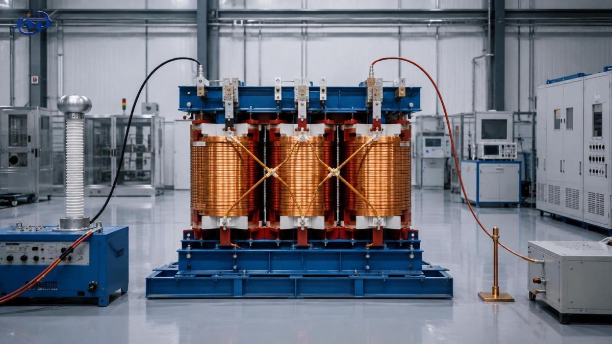
Electrical routine tests that should be witnessed or reviewed
The exact test set depends on the transformer design and contract, but several routine tests form the practical core of factory acceptance. The test report must identify the transformer by serial number, show the test conditions, state the instrument or test arrangement used, and include actual recorded results rather than a generic “pass” statement.
Test values need interpretation. Small phase differences may reflect test lead resistance, conductor geometry, or temperature. They should not be dismissed automatically, but neither should they be judged in isolation. A useful review asks whether the result is internally consistent, whether it agrees with the approved design, and whether the manufacturer has explained any departure from expected behavior.
Pay close attention to re-tests. A repeated test is not automatically grounds for rejection, but it must have a documented reason. A corrected connection error, for example, is different from a dielectric failure followed by repair. The report should show the original event, corrective action, inspection after repair, and final result. Removing that history from the acceptance record prevents the buyer from assessing the real risk.
Mechanical, safety, and shipment checks
Electrical performance can be lost during transport if the transformer is not prepared correctly. Inspect the tank, radiators where fitted, bushings, terminal compartments, gaskets, welds, fasteners, lifting lugs, wheels, and pressure-relief or protective devices appropriate to the design. There should be no oil seepage, damaged porcelain or polymer insulation, unprotected terminal threads, missing earth terminals, or paint defects that expose base metal in a corrosive environment.
For a liquid-filled transformer, verify the fluid level or shipping condition specified for transport, valve positions, sealing arrangements, and any pressure or gas-related shipping instructions. For dry-type units, inspect enclosure integrity, ventilation openings, internal clearance, and protection against moisture and impact. In either design, confirm that lifting points are clearly marked and that the shipping package prevents movement of vulnerable accessories.
Safety review should include practical details that are often left until site installation: accessible earthing points, durable high-voltage warning labels, correct phase and terminal identification, safe access to tap-changing controls, and adequate segregation of live connections once installed. These are not cosmetic requirements. Ambiguous markings and inaccessible earth points create avoidable risk during commissioning and maintenance.
Do not confuse certification paperwork with acceptance evidence
Certification and compliance documents can demonstrate that a product family, material, or component has been assessed under a stated scheme. They do not replace serial-number-specific factory records. A buyer should request the documents required by the project, but should keep them separate from the transformer’s own inspection and test evidence.
The final document pack should normally include the approved outline and connection drawings, nameplate data, routine test report, packing list, operating and maintenance instructions, warranty terms, and records for specified components or accessories. When a project requires additional tests, inspection reports, or certificates, those deliverables should be listed in the purchase specification rather than assumed.
Manufacturers with disciplined design control, documented manufacturing processes, and a rigorous quality system are better positioned to provide this traceability consistently. Jinshida Electric Power Technology Co., Ltd. applies this quality-focused approach to power transmission and distribution equipment for grid, industrial, renewable-energy, and infrastructure applications.
Where the site duty changes the FAT priorities
The factory test should reflect the system the transformer will serve. A standard utility feeder, a plant with large motor loads, and a renewable-energy site may each impose different operational concerns. For example, a transformer feeding sensitive electronic loads may require more attention to harmonic duty, earthing arrangement, and impedance coordination. A unit intended for parallel operation requires careful confirmation of voltage ratio, vector group, impedance, and tap position compatibility with the companion transformer.
Projects combining a transformer with battery storage deserve the same interface discipline. An outdoor system such as the 125kW/261kWh Commercial & Industrial Energy Storage System can operate at 380 V or 400 V AC and may be used for load shifting, backup supply, or renewable-energy integration. The transformer FAT is not a test of the storage cabinet, but the buyer should ensure that transformer secondary voltage, vector group, protection philosophy, earthing arrangement, and expected bidirectional power flow align with the overall electrical design.
A practical release checklist
Shipment approval should be withheld until the buyer can answer “yes” to each of these questions:
- Does the serial-numbered unit match the approved rating, voltage, taps, vector group, impedance, terminals, and accessories?
- Has the copper winding assembly been inspected or supported by adequate production and material traceability records?
- Are routine test results complete, legible, internally consistent, and tied to the required technical standard?
- Have failed, repeated, or unusual test events been fully documented and closed?
- Are the nameplate, markings, earthing provisions, warning labels, and operating controls suitable for safe installation and maintenance?
- Has the transformer been protected for transport, including vulnerable bushings, accessories, sealing surfaces, and lifting provisions?
- Does the final document pack contain the records needed for commissioning, maintenance, and future fault investigation?
A copper-wound transformer should not be accepted simply because it is new, visually intact, or accompanied by a standard certificate. Acceptance is justified when construction, test evidence, application requirements, and shipment condition tell the same story. That discipline identifies correctable problems while the transformer is still at the factory, where resolution is far less disruptive than after energization.

Get a Quote
Regardless of whether you require general advice or specific support, we are happy to help you.
Send Us Your Inquiry Today

Jinshida Electric remains committed to contributing to global energy development through professional manufacturing and superior service.