





Why Do Oil Cooled Transformers Overheat? Causes, Checks, and Corrective Actions
An overheating oil cooled transformer is rarely “just a temperature problem.” It is usually a warning that heat is being generated faster than the cooling system can remove it, or that the transformer’s internal thermal path has been compromised. If the condition is allowed to continue, insulation aging accelerates, oil quality declines, winding damage becomes more likely, and an avoidable service call can turn into a forced outage.
For after-sales maintenance personnel, the priority is not simply to lower the indicated temperature. The real task is to determine why the temperature rose, whether the reading is trustworthy, and which corrective action will restore a safe operating margin without creating a new risk. A fan that has stopped, a radiator coated in dust, a blocked oil path, an overloaded secondary circuit, or moisture-contaminated oil can all produce a similar alarm—but they demand very different responses.
Start with the temperature pattern, not the alarm alone
Before opening a cabinet or isolating equipment, review the operating record. A single high-temperature event after a sudden load increase is different from a slow rise over several weeks. Likewise, top-oil temperature, winding temperature, ambient temperature, load current, fan status, and oil level should be considered together.
A useful field question is: Does the temperature rise match the load and ambient conditions? If the transformer has been operating near its design limit on a hot day, a higher reading may be understandable. If the load is moderate, ambient conditions are normal, and temperature still climbs, the cooling system or internal condition deserves immediate attention.
- High temperature with high load: investigate overload, unbalanced phases, harmonics, and inadequate cooling capacity.
- High temperature with normal load: check fan operation, radiator condition, oil circulation, sensor accuracy, and internal losses.
- Rapid temperature increase: treat it as urgent; look for cooling equipment failure, a pump issue where applicable, a shorted component, or abnormal circulating current.
- Gradual long-term increase: inspect for fouled radiators, aging oil, deteriorated contacts, reduced airflow, and load growth that was never reflected in the original cooling design.
Do not assume the indicator is correct simply because it is energized. Compare local gauges, controller values, SCADA data, and, where safe and practical, an infrared temperature scan. A failed sensor or poorly configured controller can create a false alarm; more dangerously, it can also conceal a real overheating condition.
Where the heat usually comes from
1. Continuous overload or an uneven phase load
Load losses rise sharply as current increases. Even when the total kVA seems acceptable, one heavily loaded phase can run hotter than the others and create localized stress in leads, bushings, tap connections, and windings. In commercial facilities, data centers, mining operations, and renewable-energy installations, nonlinear loads can add harmonic current that increases eddy-current and stray losses beyond what a simple current reading suggests.
Measure phase currents on the low-voltage and high-voltage sides, then compare the results with the transformer nameplate rating and the permitted loading profile. Check the neutral current where relevant. A high neutral current, unexplained phase imbalance, or distorted current waveform should lead to a review of the connected load—not just a decision to add cooling.
Forced cooling may allow certain transformer designs to carry increased load for defined conditions, but it is not a blanket cure for an undersized unit or a permanently overloaded installation. Sustained operation beyond the intended thermal capability shortens insulation life, even if no trip occurs.
2. Radiators cannot release heat effectively
Radiators work only when heat can move from the oil through the radiator surface and into the surrounding air. Dust, cotton fibers, salt deposits, industrial fumes, paint overspray, insects, vegetation, or poorly planned enclosure walls can reduce that heat exchange. In outdoor locations, one side of a radiator bank may also receive much less airflow than expected because of nearby structures.
Look for uneven radiator temperatures with an infrared camera. A radiator that remains much cooler than neighboring sections while oil temperature is high may have restricted oil flow, a closed valve, trapped air, or an internal blockage. By contrast, uniformly hot radiators with little temperature reduction between inlet and outlet often point to weak airflow or insufficient cooling capacity.
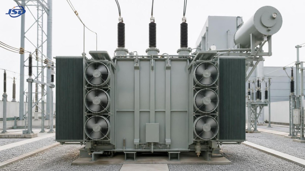
Cleaning should be done carefully. Avoid deforming fins, driving contamination deeper into narrow passages, or spraying water where it can enter electrical compartments. Verify that all radiator isolation valves are fully open after any maintenance activity; partially closed valves are a surprisingly common cause of poor heat dissipation after commissioning or repair.
3. Cooling fans, pumps, or control circuits have failed
On an oil cooled transformer equipped with forced-air or forced-oil cooling, mechanical cooling equipment is part of the thermal protection system—not an accessory. A fan may have a failed motor, seized bearing, damaged blade, tripped overload relay, failed contactor, blown fuse, defective thermostat, or incorrect automatic/manual control setting. A pump-equipped system may suffer from low flow, reverse rotation, vibration, leakage, or a blocked strainer.
Do not inspect fans only by listening from a distance. Confirm each fan’s rotation direction, airflow direction, current draw, vibration level, and start/stop response at the programmed temperature setpoint. A fan rotating backward can appear to run normally while providing little useful airflow. When several fans are installed, verify that the controller stages them correctly rather than repeatedly starting only one bank.
For pumped oil systems, compare inlet and outlet temperatures, inspect differential pressure or flow indication if provided, and examine the pump for abnormal noise. Where site procedures permit, review the motor protection history. Repeated overload trips may be a symptom of a mechanical problem rather than an electrical one.
4. Oil circulation is restricted or the oil condition has declined
Transformer oil provides insulation and carries heat away from active parts. Low oil level, sludge formation, moisture ingress, oxidation, or restricted circulation can reduce both functions. Darkening oil alone is not a complete diagnosis, but it is a prompt to test rather than guess.
Check the conservator level or oil-level indicator with temperature compensation in mind. A low reading may result from a leak, incorrect gauge operation, or an abnormal pressure condition. Inspect flanges, valves, radiators, bushings, gaskets, and cooling pipework for seepage. Also examine breathers and seals: a saturated breather or damaged seal can allow moisture into the system, gradually weakening dielectric performance and accelerating oil deterioration.
For a transformer that has operated hot or shows a persistent thermal trend, arrange oil analysis appropriate to the maintenance plan. Typical testing may include moisture content, dielectric breakdown voltage, acidity, interfacial tension, dissolved gas analysis, and furan analysis for paper insulation condition. Dissolved gas results are particularly important when overheating may be internal, because localized hot spots can produce characteristic gas patterns.
5. Internal electrical defects are generating abnormal losses
Not every overheating problem begins outside the tank. Loose or degraded connections, tap changer contact wear, circulating currents, core grounding faults, winding deformation, shorted turns, or poor contact resistance can create localized heating that cooling fans cannot solve. These faults may initially appear as a general temperature rise, but they often develop warning signs: abnormal gas results, unusual sound, repeated protection operations, a sudden change in no-load current, or one phase behaving differently from the others.
If external checks do not explain the temperature, avoid repeated re-energization merely to “see if it settles.” Escalate the investigation. Depending on the transformer type and site procedures, diagnostic work may include insulation resistance testing, winding resistance measurement, turns-ratio testing, sweep frequency response analysis, thermographic inspection of accessible connections, and a detailed review of dissolved gas trends.
A practical on-site inspection sequence
When a temperature alarm is active, a calm, repeatable sequence reduces the chance of missing the obvious while keeping personnel safe. Follow the site’s lockout, arc-flash, and energized-work requirements throughout.
- Confirm the alarm: compare temperature indicators and review recent load, ambient, and cooling-stage records.
- Assess loading: record all phase currents, voltage conditions, power factor where available, neutral current, and evidence of harmonics.
- Inspect the cooling path: check fan operation, pump condition, radiator cleanliness, airflow clearance, valve positions, and oil level.
- Use thermal imaging: scan bushings, cable terminations, radiator banks, fan motors, control panels, and accessible connections for uneven heating.
- Check controls and auxiliaries: verify thermostat settings, fan staging, contactors, motor protection devices, supply voltage, and alarm logic.
- Review oil and diagnostic history: compare present findings with prior oil test results, prior load data, and previous maintenance notes.
- Decide on operating status: reduce load, activate available standby cooling, isolate for repair, or arrange deeper testing based on the severity and evidence.
Documenting actual readings matters. “Fans checked OK” is much less useful than “Fan bank 2 failed to start at the programmed setpoint; motor supply present, contactor coil energized, motor winding resistance abnormal.” Clear records make repeat faults easier to identify and help engineering teams distinguish a site condition from an equipment issue.
Corrective actions should match the root cause
When replacement should be part of the discussion
Repeated overheating can indicate that an existing oil-filled design no longer fits the installation. This is especially relevant where load density has increased, ventilation is limited, fire-safety requirements have changed, or oil containment has become a concern. A replacement decision should consider not only rated capacity, but also ambient conditions, harmonic load, available room ventilation, maintenance access, fault level, and future expansion.
For indoor substations and applications where fire performance and reduced maintenance exposure are priorities, a cast-resin alternative may be worth evaluating. Jinshida Electric Power Technology provides transmission and distribution equipment for industrial, infrastructure, new-energy, and commercial power applications; its 35kV Three-Phase Cast Resin Dry-Type Distribution Transformer is designed for 35 kV/0.4 kV distribution duties in settings such as industrial plants, hospitals, data centers, mining operations, and renewable-energy systems. Its temperature protection and control system supports clearer thermal monitoring, while its cast-resin construction removes the need for insulating oil in the transformer itself.
This does not mean every hot oil-filled unit must be replaced with a dry-type transformer. A well-maintained oil cooled transformer remains an effective solution in many installations. The key is to make the choice from a documented root-cause assessment, not from the pressure of a single alarm event.
Keep the next alarm from becoming the same service call
The best corrective action includes prevention. Establish trend reviews for top-oil and winding temperatures, phase loading, fan run hours, oil-test results, and ambient conditions. Clean radiators on a schedule based on the actual environment rather than a generic calendar interval. Test automatic cooling controls before peak-load seasons. After any repair, run a functional check under controlled conditions and confirm that temperature behavior has returned to the expected pattern.
Overheating is often the first visible sign of a problem that has been developing quietly. By checking load, airflow, oil circulation, controls, and internal condition in a disciplined order, maintenance teams can protect insulation life, reduce unplanned downtime, and return the transformer to stable operation with confidence.

Get a Quote
Regardless of whether you require general advice or specific support, we are happy to help you.
Send Us Your Inquiry Today

Jinshida Electric remains committed to contributing to global energy development through professional manufacturing and superior service.