





When should an open type diesel genset manufacturer provide drawings?
When a standby-power package is being coordinated with civil, electrical, and mechanical work, a missing drawing can stop progress even when the generator itself is technically suitable. The foundation may be poured before the skid dimensions are confirmed, cable trenches may be routed into the wrong side of the room, or ventilation openings may conflict with radiator discharge. For that reason, an open type diesel genset manufacturer should not wait until the equipment is ready to ship before issuing drawings.
The practical answer is that drawings should be provided at four decision points: during quotation, after technical approval, before production reaches an irreversible stage, and before delivery. The detail required changes at each stage. Early documents support planning; approved documents freeze interfaces; production drawings prevent deviation; and final documents support installation, testing, and maintenance. Project managers should treat drawing release as a controlled engineering deliverable, not as a sales attachment.
Drawings needed during quotation and bid evaluation
At quotation stage, the objective is not to obtain every internal manufacturing detail. The project team needs enough information to decide whether the genset can physically and electrically fit the proposed system. A preliminary general arrangement drawing is usually the most useful document at this point.
For an open-type unit installed inside a generator room, the preliminary drawing should show the overall length, width, height, approximate operating weight, lifting points, engine-radiator orientation, control panel location, exhaust outlet direction, fuel connection locations, and main power-cable entry arrangement. Even where dimensions are marked as preliminary, they allow the design team to reserve practical space around the machine.
This early release matters most when the equipment room is tight or shared with transformers, low-voltage switchgear, fuel systems, battery storage, or fire-protection piping. A generator set cannot be assessed only by its rated kVA. A compact footprint may still require large maintenance clearances, a radiator airflow path, silencer routing, and unobstructed access for removal of engine components.
The quotation package should also identify major electrical assumptions. These often include rated voltage and frequency, power factor, phase arrangement, alternator terminal configuration, breaker frame or rated current range, earthing point, control interface, and whether the unit is intended for standby, prime, or continuous duty. Without these assumptions, the electrical consultant cannot reliably compare the generator with the switchgear and automatic transfer arrangement.
What a preliminary drawing should not be used for
A preliminary drawing is suitable for budget design and spatial coordination, but it should not be used to release concrete works, fabricate cable supports, or finalize louver sizes. Model selection, fuel tank configuration, controller arrangement, alternator frame, and accessory options can still change after technical clarification. The drawing should clearly carry a revision number and a status such as “for review” or “for tender reference” so that no party mistakes it for an approved-for-construction document.
After order placement: issue documents for technical approval
Once the order is placed and the required generator rating, voltage, duty, and accessories have been agreed, the manufacturer should issue a more complete submittal package for approval. This is the stage at which the project team should identify conflicts before procurement and fabrication are locked in.
An approved general arrangement drawing should show confirmed dimensions and weights, mounting-hole positions, center of gravity where relevant, service access zones, and the exact locations of external interfaces. It should distinguish between the base frame, day tank if supplied, acoustic accessories if any, control panel, battery system, radiator, exhaust connection, and output terminal box.
For indoor open-type installations, ventilation information is particularly important. The drawing or associated data sheet should identify radiator airflow direction, recommended inlet and outlet arrangement, approximate air volume requirement, and any restrictions on ducting. A generator room can appear adequately sized on a floor plan yet still suffer overheating when the hot discharge air is allowed to recirculate toward the radiator intake. Civil and HVAC teams need these details before louvers, ducts, and weather hoods are finalized.
The technical approval package should normally include the following documents:
- A confirmed general arrangement drawing with plan, side, and front views.
- A foundation or base-frame layout showing fixing points and loading locations.
- An electrical single-line or connection diagram for the generator output and control interfaces.
- A terminal schedule identifying power terminals, remote start terminals, alarm contacts, communications ports, and earthing points.
- Fuel, exhaust, cooling, and ventilation interface information applicable to the selected configuration.
- A data sheet listing ratings, operating conditions, protection functions, and supplied accessories.
The manufacturer does not need to take over responsibility for the building design. However, the supplied information must be sufficiently clear for the engineer responsible for the room, cable system, and associated switchgear to complete that design without guessing at interfaces.
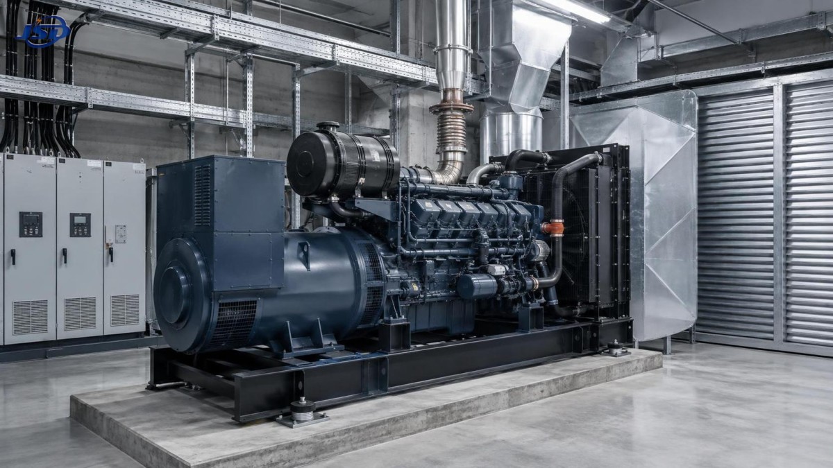
Freeze the critical interfaces before production
The most costly drawing disputes usually arise when an approved design change is communicated informally but not incorporated into a revised drawing. A request to move the control panel, change the breaker arrangement, reverse the radiator orientation, add remote monitoring, or alter the fuel tank position can affect dimensions, cable routing, and installation work. Before production begins on those affected elements, the supplier should issue a revised drawing with a clear revision cloud or change note.
Project managers should pay close attention to the boundary between “approved” and “acknowledged.” A comment such as “please relocate cable entry” should not be treated as resolved simply because it appears in an email chain. The revised document should show whether the request has been accepted, rejected, or incorporated with a different arrangement. Where the requested change creates a technical limitation, that limitation should be stated in writing.
There are several interfaces that deserve a direct cross-check meeting or document review:
- Power connection: Confirm cable-entry direction, terminal size, phase sequence, neutral treatment, breaker rating, and space for bending large cables.
- Control integration: Confirm start/stop logic, automatic transfer switch signals, common alarm contacts, emergency-stop arrangement, and communication requirements.
- Mechanical installation: Confirm foundation dimensions, anti-vibration mounting arrangement, lifting access, exhaust route, and fuel line connection points.
- Room environment: Confirm ventilation openings, radiator discharge path, maintenance access, lighting access, drainage, and safe battery servicing space.
This review is also where the generator package should be considered as part of a broader power architecture rather than as an isolated machine. Some sites combine a diesel standby source with solar generation, inverter systems, or battery-supported loads. Where a low-voltage energy-storage system is included, the electrical drawings need to show isolation, protection, communication boundaries, and the intended operating logic between the generator and inverter equipment.
For example, a modular battery arrangement such as the 51.2V Stackable LiFePO4 Energy Storage Battery may be used in residential, off-grid, or light commercial energy-storage configurations. Its 51.2V nominal voltage, CAN/RS485 communication options, and expandable 5.12kWh to 20.48kWh system capacity are relevant only when the generator, inverter, and battery system are designed to operate together. The generator drawing package should not imply direct compatibility unless the connection method, inverter role, charging limits, and protection arrangement have been confirmed in the system design.
What should be available before dispatch
Before shipment, the project team needs final documentation that matches the manufactured unit, not merely the originally approved concept. This is especially important when equipment has been held in storage, shipped to a remote site, or installed by a contractor who was not involved in the early design review.
Final drawings should carry the final revision status and identify the supplied configuration. At a minimum, the package should include the final general arrangement, electrical schematic or wiring diagram appropriate to the supplied controls, terminal details, operation and maintenance documentation, and identification of installed major components. If the generator has non-standard interfaces or site-specific accessories, those should be clearly reflected.
For an open type diesel genset manufacturer, pre-delivery documents should also help the receiving team prepare for unloading. Confirmed shipping weight, lifting points, lifting restrictions, and center-of-gravity information reduce the risk of using unsuitable handling equipment. A general arrangement drawing without handling information may be adequate for room planning but insufficient for a difficult offloading operation.
Final documentation should be issued early enough for installation planning. Providing it only after the unit arrives creates avoidable pressure: the contractor may need to position the set, terminate cables, arrange ventilation, and connect exhaust equipment while still waiting for terminal or interface details. The document release date should therefore be linked to the project installation schedule, not merely to the dispatch date.
Drawing content that prevents field conflicts
Not every drawing has equal value. The most useful drawings answer the questions the installation team will actually face. A plan view alone rarely resolves those questions. Dimensions should be tied to defined reference points, and interface points should be identified with enough clarity that field personnel do not have to infer their positions from a scaled image.
Dimensions alone are not enough. Drawings should state whether service clearances are mandatory, recommended, or dependent on the final maintenance method. A manufacturer may show an ideal clearance around the engine, but a constrained plant room may require an alternative access approach. That decision should be resolved during approval, not discovered after walls, cable trays, and pipework are complete.
Set a drawing schedule in the purchase order
The simplest way to avoid late documentation is to make drawing milestones part of the purchase order and project schedule. Instead of asking generally for “all technical documents,” specify what is needed, who will review it, and the expected release condition.
A workable sequence may require a preliminary general arrangement within the quotation period, an approval package after receipt of the confirmed order data, revised drawings after comments are closed, and final as-built or final configuration documents before dispatch. The schedule should allow review time on both sides. Fast approval is useful only when the reviewer has checked electrical, civil, ventilation, fuel, and control interfaces rather than signing off on dimensions alone.
Document control is equally important. Every drawing should have a number, revision, date, status, and a record of issued recipients. When more than one revision exists, site teams should be instructed which version governs construction. A superseded drawing left in a shared folder can cause the same damage as no drawing at all.
When additional drawings are justified
Some projects need more than a standard general arrangement and connection diagram. Additional drawings are justified when the installation includes a remote radiator, custom base tank, unusual cable routing, parallel generator operation, synchronization panels, external fuel-transfer equipment, containerized auxiliaries, or integration with a battery and inverter system. The complexity is not defined by the generator rating alone; it is defined by the number of interfaces that must work together.
In these situations, the project manager should ask which party owns each interface. The genset supplier may provide generator-side connection points, while the electrical contractor designs cables, the mechanical contractor designs exhaust and ventilation ducts, and the controls specialist defines supervisory logic. Clear drawings make those boundaries visible. They do not replace coordination, but they give coordination a reliable technical basis.
Drawings should therefore arrive before each irreversible project decision: before space is reserved, before foundations and openings are built, before manufacturing is committed, and before the generator is installed. When documentation follows that sequence, the generator set is far less likely to become the source of a late-stage conflict in an otherwise well-planned power system.

Get a Quote
Regardless of whether you require general advice or specific support, we are happy to help you.
Send Us Your Inquiry Today

Jinshida Electric remains committed to contributing to global energy development through professional manufacturing and superior service.