





What clearance does a dry type substation transformer need indoors?
Planning an indoor installation for a dry type substation transformer involves much more than fitting the unit into an available electrical room. The clear space around the transformer affects cooling airflow, safe access to energized equipment, cable routing, inspection work, fire protection coordination, and the practical ability to replace components years after commissioning.
For project managers, the most important answer is this: there is no single universal indoor clearance dimension that applies to every dry-type transformer. The required clearance must be determined by the transformer manufacturer’s installation drawing, the applicable electrical and building codes, the room ventilation design, voltage level, enclosure construction, and the maintenance strategy for the site.
That said, a well-planned layout follows several consistent principles. Treat clearance as a coordinated design issue—not a last-minute space allowance after switchgear, cable trays, and HVAC ducts have already occupied the room.
Start by separating three different kinds of clearance
Many installation problems arise because “transformer clearance” is discussed as though it were one measurement. In practice, the design team needs to consider at least three separate zones around an indoor transformer.
1. Ventilation and heat-dissipation clearance
A dry-type transformer releases heat into the surrounding room. Unlike an oil-filled unit, it does not use liquid insulation and cooling, so its thermal performance depends heavily on air movement around the windings and enclosure. If intake or exhaust openings are blocked by walls, panels, cable trays, stored materials, or adjacent equipment, the transformer may operate at a higher temperature than intended.
The manufacturer’s instructions should define minimum unobstructed distances around ventilation grilles, cooling ducts, and top-mounted exhaust paths. These distances are especially important for ventilated dry-type designs and for units with forced-air cooling provisions. Leaving a generous service aisle is not enough if warm air becomes trapped above the transformer or recirculates directly back into the air intake.
As a practical rule, do not design the room around a presumed “standard” side gap. Review the transformer’s heat loss, cooling method, enclosure ventilation arrangement, room volume, ambient temperature assumptions, and any mechanical exhaust system together. A clearance that looks acceptable on a floor plan can still be inadequate if the room has a low ceiling or poor exhaust path.
2. Electrical working space
Working clearance is the protected area required for personnel to safely inspect, test, operate, or service energized electrical equipment. It is not simply empty floor space. Its depth, width, and height are usually governed by the local electrical code and depend on voltage, exposed live parts, whether grounded surfaces are opposite the equipment, and the arrangement of nearby panels or switchgear.
For example, the clearance in front of a transformer’s low-voltage termination compartment may need to satisfy electrical working-space rules even when the transformer body itself is physically farther from the wall. The same applies to high-voltage cable boxes, primary switches, and adjacent medium-voltage gear.
Project teams should verify these requirements with the authority having jurisdiction (AHJ) and the project’s electrical engineer. In many jurisdictions, standards such as NFPA 70 / NEC or local equivalents influence the required access space, but the final interpretation belongs to the applicable code and approving authority.
3. Maintenance and replacement clearance
The third zone is often underestimated because it may not appear as a minimum code dimension. Technicians need room to remove access panels, torque terminations, perform insulation testing, inspect winding connections, clean ventilation passages, and work safely with test equipment. If cooling fans, temperature sensors, or control components are fitted, they must also be reachable without dismantling surrounding infrastructure.
Consider the future as well. Can the transformer be moved out of the room if a major repair or replacement is required? Is there a removable wall panel, equipment door, lifting beam, hatch, or corridor with sufficient turning radius? A transformer room that works only on installation day can create a costly operational problem later.
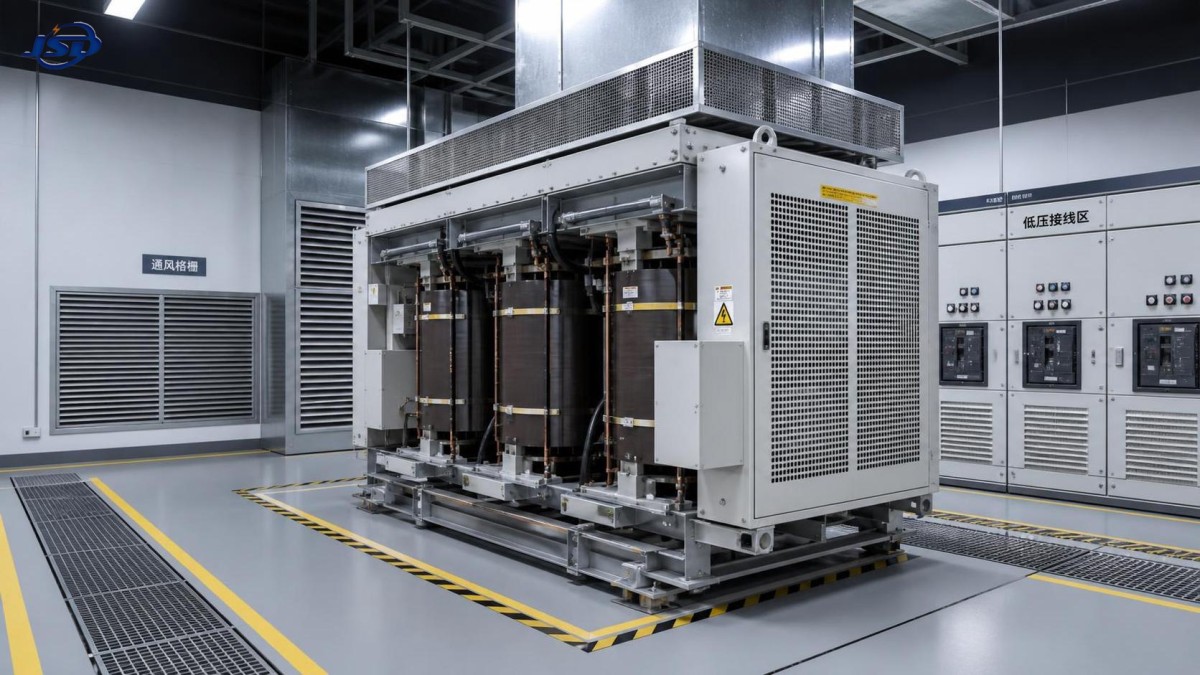
What usually determines the final indoor clearance?
The most reliable approach is to build the layout around the approved manufacturer data rather than forcing the transformer into a predetermined footprint. The following factors should be reviewed during design coordination.
Room ventilation is often the real limiting factor
In an indoor transformer room, clearance and ventilation cannot be separated. A transformer may have sufficient physical distance from walls but still experience poor cooling because heat accumulates in the upper part of the room. This is common where a compact substation room has limited ceiling height, sealed architectural louvers, or exhaust fans selected without reference to transformer losses.
A useful design review follows the heat path: cool air should enter at a lower level, pass through or around the transformer enclosure as intended, rise as it warms, and exit without being drawn back toward the intake. When several transformers are installed in the same room, their exhaust air should not feed neighboring units. The issue becomes more critical where units operate near rated load for long periods.
Do not allow cable trays, fire-protection piping, ventilation ducts, or communication cabinets to obstruct top discharge areas. Similarly, avoid placing a dry-type transformer directly beneath a low structural beam unless the manufacturer confirms that the available space will not impair cooling or access.
A practical layout approach for project managers
Instead of asking, “How close can we put the transformer to the wall?” ask, “What clear envelope must remain usable throughout the transformer’s life?” This small change in perspective improves coordination between civil, mechanical, electrical, and operations teams.
- Obtain the approved outline drawing early. Request overall dimensions, shipping weight, lifting points, terminal locations, panel swing areas, ventilation openings, and installation clearances before finalizing the electrical-room plan.
- Mark operational zones on the layout. Show airflow zones, electrical working space, door opening arcs, cable-bending areas, and maintenance access separately. Combining them into one vague “clear area” can hide conflicts.
- Check vertical space as carefully as floor space. Dry-type transformers need a clear heat path above the enclosure. Verify clearance to ceilings, beams, trays, ducts, and lighting fixtures.
- Coordinate cable entry before pouring foundations. Bottom-entry and side-entry cable arrangements can require substantial bending radius and pulling space, particularly for medium-voltage cables.
- Plan for safe handling. Confirm the route from unloading point to transformer room, floor loading, doorway dimensions, and whether lifting equipment can be used without compromising the building structure.
- Protect the space after handover. A compliant room can become unsafe when it turns into a storage area. Include signage, housekeeping rules, and access control in the operating plan.
Common clearance mistakes that lead to redesign
Using a generic gap from an old project. Similar transformer capacity does not guarantee similar enclosure dimensions, cooling requirements, or terminal arrangements. Manufacturer instructions should always take priority over informal rules of thumb.
Allowing a clear aisle but blocking ventilation. This happens when cabinets or trays are positioned above, behind, or beside air openings. The room may look orderly while the transformer runs hotter than expected.
Ignoring the door swing of adjacent equipment. Switchgear doors, transformer access panels, and room doors can compete for the same space. During an outage, this creates delays exactly when crews need fast access.
Designing only for commissioning. Initial cable termination may be possible, but future inspection, retesting, fan replacement, or transformer removal becomes difficult. Long-term maintainability is a capital-project issue, not merely an operations concern.
Assuming fire-rated walls solve every fire-safety issue. Fire separation, smoke management, detection, emergency access, and local building requirements all need consideration. The transformer’s dry-type construction can simplify certain risk considerations, but it does not remove the need for a coordinated fire-safety design.
When the indoor transformer supports renewable-energy infrastructure
Although wind projects frequently use outdoor step-up transformers, the same planning discipline is valuable where renewable-energy facilities include indoor substations, auxiliary distribution rooms, control buildings, or grid-connection equipment. Interfaces between generation assets and the electrical network are unforgiving of poor access and inadequate thermal design.
For outdoor wind turbine step-up applications, Jinshida’s Transformer for Wind Power Generation is designed for 630 kVA to 5000 kVA applications, with 10 kV, 20 kV, or 35 kV high-voltage options and a 0.69 kV low-voltage side. Its IEC 60076-oriented configuration, copper windings, and suitability for demanding operating environments address a different installation context from an indoor dry type substation transformer. However, both applications benefit from the same early coordination of thermal conditions, cable access, maintenance routes, and site-specific electrical requirements.
Before approving the construction drawing
A sound indoor transformer layout should be confirmed against four documents: the manufacturer’s certified installation manual, the electrical single-line and equipment layout, the mechanical ventilation calculation, and the applicable code review. If any one of these documents is missing, the clearance decision is not yet fully supported.
Ask the design team to document the minimum clearances on the coordinated drawing rather than leaving them as notes in separate manuals. This makes it easier for contractors to avoid late changes and for facility teams to preserve access after the project enters service.
The right clearance for a dry type substation transformer is therefore not a single number—it is a verified operating envelope. When ventilation, electrical safety, maintenance access, and replacement logistics are addressed together, the transformer room becomes easier to commission, safer to service, and far less likely to create avoidable downtime over its working life.

Get a Quote
Regardless of whether you require general advice or specific support, we are happy to help you.
Send Us Your Inquiry Today

Jinshida Electric remains committed to contributing to global energy development through professional manufacturing and superior service.