





What causes voltage instability in a diesel open frame genset?
A diesel open frame genset may appear to be running normally while the output voltage drifts, surges, or drops whenever a motor starts, a welding load is connected, or the load changes. This is more than an electrical nuisance: unstable voltage can trip drives, overheat contactors, damage sensitive controls, and make a standby power system unreliable when it is needed most.
The quickest way to narrow the fault is to separate frequency instability from voltage-regulation instability. Frequency follows engine speed; voltage is primarily controlled by excitation, the AVR, alternator condition, sensing circuits, and load characteristics. When both frequency and voltage move together, start with the engine and governor. When frequency remains stable but voltage wanders, investigate the AVR, excitation circuit, alternator, sensing wiring, and connected load.
Read the symptom before replacing parts
Voltage complaints are often reported as “low voltage” or “unstable output,” but the pattern matters. A steady low reading has a different cause from a rapid hunting voltage, and a fault that occurs only under load is different from one seen at no load. Before changing an AVR or adjusting the governor, record voltage, frequency, engine speed if available, load current on each phase, and the moment when the problem starts.
Use instruments known to be accurate. A low-cost meter may give misleading readings on a waveform distorted by electronic loads. Compare the controller display with a calibrated handheld meter at the generator terminals, then measure again at the downstream distribution point. A difference between those locations points toward cables, breakers, terminals, or transfer equipment rather than the generating end.
Engine speed fluctuations are a primary cause
A synchronous alternator produces frequency in direct relation to rotational speed. In practical terms, a 50 Hz set rated at 1500 rpm or a 60 Hz set rated at 1800 rpm must hold close to its rated speed. When the speed repeatedly overshoots and undershoots, frequency changes first, and the AVR may react to the accompanying voltage change. This can make the electrical fault look worse than the original mechanical cause.
Watch the frequency display while the engine is warm and unloaded. A slow rhythmic movement may indicate governor hunting. A sharp dip when a load is applied can indicate insufficient fuel response, restricted fuel flow, air in the fuel line, a weak actuator signal, or an aggressive load step. On mechanically governed engines, inspect linkages for binding, free play, weak return springs, and incorrect adjustment. On electronically governed units, check actuator connectors, speed-sensor wiring, controller supply voltage, and any active alarms or parameter changes.
Fuel quality and delivery should not be overlooked. A restricted filter, water contamination, blocked tank vent, damaged flexible hose, or air leak on the suction side can cause intermittent speed loss. The engine may recover quickly enough that operators notice only flickering lights or a changing panel voltage. Confirm that the fault remains after basic fuel-system checks and that the engine reaches stable operating temperature before making governor adjustments.
Do not correct a speed problem by turning up the AVR voltage adjustment. That may temporarily improve one meter reading while the frequency remains outside the required range. Motors, chargers, UPS bypass circuits, and timing-sensitive equipment can still be affected.
AVR and excitation faults can produce a stable-speed voltage problem
The automatic voltage regulator compares sensed output voltage with its target and adjusts field excitation to maintain the alternator output. A failed AVR is possible, but it should not be assumed before its supply, sensing leads, and field connections have been checked. Loose terminals, oxidized connectors, broken conductors inside vibration-prone harnesses, and incorrect reconnection after service are frequent causes of irregular regulation.
Begin with a safe shutdown and isolation procedure. Inspect the AVR terminal block, sensing fuses where fitted, plugs, harness clamps, and generator terminal connections. Look for heat discoloration, loose crimp terminals, moisture, oil ingress, rubbed insulation, and signs that a conductor has been pulled tight by vibration. Tighten connections to the equipment manufacturer’s torque requirements rather than guessing; over-tightening can damage smaller control terminals.
With the set operating and proper electrical safety controls in place, verify that the AVR receives the correct sensing input according to the alternator connection. A missing or intermittent sensing phase can make the regulator drive excitation incorrectly, often causing high voltage, low voltage, or cycling. Incorrect jumper settings for 50 Hz versus 60 Hz, voltage range, droop, or stability can create a similar symptom after an AVR replacement.
Stability and voltage trim potentiometers should be adjusted cautiously. The stability control is not a general cure for every voltage fluctuation. Excessive adjustment in either direction can cause slow hunting, rapid oscillation, or poor response to load changes. Mark the original setting before changing it, alter only one control at a time, and observe the result at no load and under a controlled load. If the voltage cannot be stabilized within a normal adjustment range, return the setting and continue the diagnosis rather than forcing the regulator to compensate for another fault.
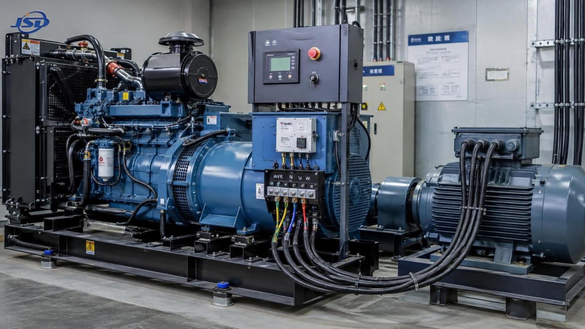
Alternator condition matters, especially after storage or overheating
A brushless alternator relies on the rotating exciter, rotating rectifier assembly, main rotor, stator windings, and AVR working as a system. Damage or deterioration in any of these parts can limit the machine’s ability to hold voltage. The fault may be constant, temperature-related, or visible only when current demand increases.
Check the alternator exterior for blocked air passages, damaged cooling screens, unusual bearing noise, and evidence of overheating. Dust, oil film, moisture, and insects can reduce insulation performance and cooling effectiveness. In open-frame installations, these risks increase because the generating end is more exposed to the surrounding environment. Water-cooled engine operation does not eliminate the need to keep the alternator itself clean and ventilated.
Loose main terminals can create voltage drop, heat, and phase imbalance. A connection may look acceptable but become resistive when it carries load. Inspect cable lugs, busbar joints, breaker terminals, neutral connections, and earth conductors. Discoloration around one terminal is a useful clue. Measure phase-to-phase and phase-to-neutral values, where the system configuration permits, rather than relying on a single displayed value.
Where manufacturer procedures and qualified test equipment are available, insulation resistance testing can help identify moisture or insulation deterioration. This test must be performed with sensitive electronic devices, AVR circuits, and connected loads isolated as required by the equipment documentation. A low insulation reading does not identify every alternator fault, but it can explain unstable or unsafe behavior after prolonged storage, condensation, or contamination.
Rotating rectifier diodes and surge suppressors should be evaluated when voltage is weak, uneven, or unable to recover under load despite a stable engine and sound AVR sensing circuit. A failed diode can reduce excitation efficiency and may lead to abnormal waveform or heating. Because access involves the rotating assembly, follow lockout procedures and use the alternator service manual for approved test values and connection details.
Load behavior often reveals the real source of instability
A genset can pass a no-load voltage test and still perform poorly when it is connected to the actual installation. Large induction motors, compressors, pumps, crushers, and poorly sequenced construction loads can impose heavy starting current. Variable-speed drives, rectifiers, UPS systems, and welding equipment can introduce harmonic currents or rapidly changing demand. The result may be a short voltage dip that is normal for the load step, or a more serious collapse that shows the generator is undersized, incorrectly configured, or carrying an unsuitable load combination.
Measure current on all three phases during the event. One heavily loaded phase may pull that phase voltage down while the other phases remain closer to normal. An apparently modest total kW load can still create problems if phase balance is poor or if the power factor and starting method were not considered. Check whether motors start direct-on-line, whether several loads start together, and whether a stalled or mechanically overloaded motor is repeatedly attempting to start.
Load rejection is equally informative. If voltage rises sharply when a large load disconnects, review AVR response and governor dynamics. If the engine speed rises at the same time, the governor may be responding too slowly or too aggressively. If frequency remains controlled but voltage overshoots, focus on AVR stability settings, sensing integrity, and excitation response.
For installations with transfer switching, inspect the ATS, contactors, and downstream terminals. A poor connection on the load side can cause erratic voltage at the equipment while generator terminal voltage remains correct. Do not overlook neutral integrity in four-wire systems. A loose or open neutral can produce dangerous phase-to-neutral voltage imbalance when single-phase loads are unevenly distributed.
A practical test sequence that avoids false conclusions
Testing should progress from simple observations to controlled electrical checks. Random adjustment of governor and AVR controls can create two faults where only one existed. The following order keeps the evidence clear:
- Confirm the complaint with a suitable meter at the genset output terminals and compare it with the controller indication.
- Run unloaded until operating conditions are stable. Record all phase voltages, frequency, and any speed indication.
- Apply load in planned increments, recording readings after each increase. Avoid connecting an uncontrolled load that could exceed the set rating.
- Determine whether frequency changes with voltage. If it does, inspect engine speed control and fuel delivery before AVR replacement.
- When frequency is steady, inspect AVR supply, sensing conductors, fuses, field wiring, settings, and grounding arrangement.
- Compare generator-terminal voltage with voltage after the breaker, ATS, and distribution cable to locate downstream voltage drop.
- Check phase current balance and identify high-inrush, nonlinear, or cycling loads.
- Only after these checks should alternator internal components be tested under the applicable service procedure.
Configuration errors after repair are more common than expected
Voltage instability sometimes begins immediately after an AVR, controller, alternator, or engine-control repair. Verify the basics before suspecting a defective new component: rated voltage selection, frequency selection, sensing lead positions, terminal links, CT polarity where droop or parallel functions are used, and governor speed target. A 230/400 V three-phase, four-wire arrangement must be connected and sensed differently from other alternator configurations. Incorrect assumptions about terminal numbering can create persistent regulation problems.
On units intended for parallel operation, load-sharing and reactive-droop circuits add further diagnostic points. An incorrectly connected current transformer or incompatible control setting can cause reactive load imbalance and unstable voltage behavior after synchronization. Disconnecting or bypassing those functions without an approved procedure can create additional risk, so compare the wiring carefully against the exact control schematic.
When replacement equipment is required, select a generator set whose voltage, frequency, speed, output configuration, and expected load profile match the site. The Open Type Diesel Generator Set range is available with 50 Hz or 60 Hz operation, 230 V / 400 V rated voltage options, electronic governor control, brushless self-excitation, and three-phase four-wire output. These features support controlled regulation, but stable site performance still depends on correct installation, load assessment, terminal integrity, and commissioning checks.
When the fault needs deeper investigation
Stop extended troubleshooting and escalate the inspection when there is smoke, burning odor, repeated breaker tripping, severe phase imbalance, exposed damaged wiring, abnormal alternator noise, or voltage outside the tolerance acceptable for connected equipment. Continued operation can turn a repairable regulator, terminal, or load issue into winding damage or equipment failure.
For recurring instability, keep a concise service record showing no-load readings, loaded readings, phase currents, frequency, ambient conditions, active loads, alarms, and every adjustment made. This makes it easier to see whether the problem follows engine temperature, a particular load, a transfer event, or a vibration-related connection. The most reliable repair is not the fastest component swap; it is the one that explains the measured behavior and remains stable through the operating conditions the diesel open frame genset is expected to handle.

Get a Quote
Regardless of whether you require general advice or specific support, we are happy to help you.
Send Us Your Inquiry Today

Jinshida Electric remains committed to contributing to global energy development through professional manufacturing and superior service.