





What causes overheating in a ventilated dry type transformer?
Overheating in a ventilated dry type transformer is not a condition to treat as a normal consequence of hard work. A modest temperature rise is expected under load, but persistent high temperature, a sudden change in temperature trend, repeated thermal alarms, or a strong hot-insulation odor usually indicates that the transformer or its installation is no longer operating within its intended thermal margin.
For after-sales maintenance personnel, the practical question is rarely “Is the transformer warm?” It is: “Why is this unit running hotter than it should, and what must be corrected before insulation damage becomes irreversible?” The answer may involve loading, airflow, connections, harmonic current, ambient conditions, or a mismatch between the transformer design and the real duty cycle. Several causes can coexist, so troubleshooting needs to move from observed symptoms to verified evidence.
Why overheating deserves immediate attention
Temperature is one of the main determinants of dry-type transformer service life. Windings, insulation systems, taps, terminals, and connection hardware all experience accelerated aging when the unit operates above its intended thermal condition. A transformer may continue supplying power while internal damage develops quietly: insulation can become brittle, winding clamping pressure may change, terminal joints can oxidize, and localized hot spots can intensify.
This matters especially in facilities where shutdown is difficult: process manufacturing, data rooms, commercial buildings, transport infrastructure, battery charging systems, and renewable-energy auxiliary systems. In these environments, a thermal alarm can be the first visible warning of a wider reliability issue. Resetting the alarm without identifying its cause may convert a manageable maintenance task into winding repair, insulation replacement, or unplanned transformer replacement.
Do not rely only on a single temperature reading. Compare the present operating condition with the transformer’s load, ambient temperature, historical trend, cooling-fan status, and readings from similar phases or similar transformers. A temperature that appears acceptable in isolation may still be abnormal when the load is low or when another phase is much cooler.
Start with the thermal pattern, not assumptions
Before opening panels or tightening connections, establish what kind of overheating event is occurring. Is the temperature high on all phases, one phase, one terminal compartment, or only at a particular load level? Does it rise gradually during the day, appear immediately after a process line starts, or remain elevated even during light load? These distinctions narrow the likely causes.
This initial classification prevents a common maintenance error: treating every high-temperature condition as a loading problem. Reducing load may temporarily lower temperature, but it does not correct a blocked air path, failing fan control circuit, poor connection, or harmonic-related eddy-current loss.
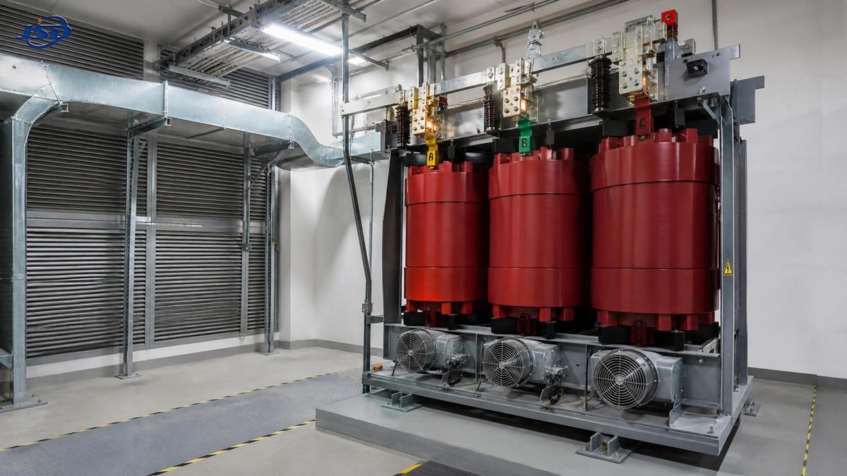
Restricted airflow is one of the most common causes
A ventilated dry type transformer depends on air movement through winding ducts and around the enclosure. Unlike an oil-filled unit, it has no liquid medium to transfer heat away from the active parts. Its thermal performance is therefore closely tied to installation clearances, air inlet condition, room ventilation, filter cleanliness where filters are used, and the actual movement of cooling air through the transformer.
Dust accumulation is often underestimated. Fine industrial dust, textile lint, metal particles, construction debris, or residue from nearby processes can settle on ventilation openings and winding surfaces. This layer reduces convective cooling and may also create tracking or insulation contamination risks. In severe environments, a unit that was correctly selected can overheat simply because cleaning intervals were designed for a cleaner site condition than the facility actually has.
Check intake and discharge openings first. Verify that cable trays, stored materials, temporary barriers, wall modifications, or nearby equipment have not restricted airflow. A transformer placed too close to a wall may recirculate its own hot exhaust air. In transformer rooms, confirm that hot air has a path to leave the room rather than accumulating near the ceiling and returning to the transformer intake.
For forced-air-cooled units, verify more than whether a fan is turning. Confirm fan rotation direction, airflow volume, fan start temperature, control relay operation, phase supply, protective devices, and fan cycling under actual operating temperature. A fan may run but deliver inadequate airflow because of obstruction, incorrect rotation, worn bearings, or a control setting that starts cooling too late. Where the design includes both natural-air and forced-air ratings, the operating load must be compared with the rating appropriate to the cooling mode currently available.
Overload is straightforward in theory, but not always in the field
Continuous operation above nameplate capacity is an obvious source of excess temperature, yet maintenance teams should be careful when interpreting current readings. Nameplate kVA, primary and secondary voltage, cooling class, tap position, and duty cycle all matter. A transformer operating within its apparent power rating can still suffer elevated losses if the current waveform is distorted or phase loading is uneven.
Measure actual phase currents and record them over a representative operating period. A brief peak may not have the same effect as a sustained overload, while repeated overload cycles can prevent the transformer from cooling down between production shifts. Load studies should account for startup periods, charging cycles, seasonal demand, and any operating pattern that differs from the original design basis.
Unbalance deserves separate attention. If one secondary phase carries significantly more current than the others, that phase winding and its associated terminals may develop a higher hot-spot temperature. The total kVA may appear acceptable, but the most heavily loaded phase can still be outside its thermal limit. Review single-phase loads, panelboard distribution, neutral current, and recent additions to the downstream system.
It is also worth confirming voltage conditions. Sustained overvoltage can increase core flux and core losses. Conversely, undervoltage may lead some downstream equipment to draw more current for the same output demand. Tap settings should match the actual supply condition and transformer design. Do not change taps casually while energized; follow the manufacturer’s instructions and site isolation procedures.
Harmonics can create heat that ordinary current readings miss
Modern electrical installations increasingly contain variable-frequency drives, rectifiers, UPS systems, welding equipment, battery chargers, electric vehicle charging equipment, LED drivers, and other nonlinear loads. These loads draw non-sinusoidal current. The resulting harmonic components can increase winding eddy-current losses, stray losses, neutral current, and local heating in conductors and metallic structural parts.
A clamp meter showing current below the nominal rating does not by itself prove that harmonic heating is absent. The measurement method, meter capability, total harmonic distortion, harmonic spectrum, and transformer design all affect the conclusion. A conventional transformer may perform satisfactorily with modest distortion but run excessively hot when the nonlinear portion of the load grows beyond the original assumption.
When overheating appears after installation of drives, rectifier systems, or large charging loads, obtain power-quality measurements rather than guessing. Record current THD, voltage distortion, phase imbalance, neutral current, power factor, and major harmonic orders under representative load. Compare the results with the transformer manufacturer’s application guidance and the facility’s power-quality requirements. The correct solution may involve load redistribution, harmonic mitigation, an appropriately rated transformer, changes to cable routing, or a revised transformer selection.
This is particularly relevant in DC power and industrial conversion applications. An Isolation and Rectifier Special Transformer may be considered where the electrical duty requires isolation and rectifier-oriented design characteristics, but the selection should be based on the actual waveform, load profile, cooling environment, voltage requirements, and protection coordination. Calling a transformer “special” does not remove the need to verify thermal performance under the site’s real operating conditions.
Loose connections create localized hot spots
Not all overheating originates inside the windings. Loose busbar joints, poorly crimped cable lugs, insufficient bolt torque, oxidized contact surfaces, damaged washers, and mismatched conductor materials can produce high-resistance heating at terminals. These faults are often localized and may progress quickly as repeated heating and cooling cycles reduce contact pressure further.
Infrared thermography is useful for identifying abnormal terminal temperatures, particularly when comparing equivalent phases under similar load. However, an infrared image is an indicator, not final proof. Surface emissivity, viewing angle, enclosure access, load stability, and reflected heat can affect the image. Follow up suspicious findings with a de-energized inspection, torque verification to the manufacturer’s specified values, and examination of lugs, busbars, insulation discoloration, and signs of arcing.
Do not simply tighten every connection to an assumed standard value. Over-torque can damage threads, deform lugs, or compromise contact hardware. Use the approved torque schedule for the specific terminal assembly, and document the before-and-after condition. If discoloration or annealing is visible, replacement of the affected hardware may be more appropriate than retightening it.
Ambient temperature and room design can erase the expected margin
Transformer ratings are based on defined ambient and cooling assumptions. A unit installed in a hot electrical room, rooftop enclosure, containerized skid, or confined basement may face conditions that differ materially from those assumptions. High outdoor temperature, solar gain, failed room exhaust fans, and heat discharged by adjacent switchgear or converters can all raise the transformer’s inlet air temperature.
The key issue is not only the room’s average temperature. Measure the air temperature near the transformer air intake and, where practical, near the hot-air discharge path. Stratification is common: a room sensor mounted at a convenient location may report an acceptable value while the transformer draws substantially hotter air from a trapped zone near the ceiling or behind an enclosure.
Review clearances against the transformer manufacturer’s installation requirements. Where multiple transformers are installed, make sure the discharge from one does not feed directly into another. For enclosed installations, assess whether ventilation louvres, ductwork, exhaust fans, and make-up air provisions remain adequate after later site modifications.
Sensor alarms should be checked, but never dismissed
Temperature sensors, monitoring relays, fan-control circuits, and communication modules can fail or drift. A false high reading is possible. Yet assuming that an alarm is false before verifying the transformer condition is risky. First compare sensor data with independent evidence: infrared readings at accessible surfaces, load level, fan operation, room temperature, and temperature differences among phases.
Where sensors are embedded in windings, their readings may not correspond directly to an external surface temperature. The important question is whether the sensor trend is credible and whether its alarm thresholds are configured according to the transformer’s insulation system and manufacturer guidance. Verify sensor wiring, relay settings, alarm versus trip thresholds, and whether a recent control-system change altered scaling or signal interpretation.
A monitoring system should support maintenance decisions, not replace inspection. Trend data is especially valuable when it shows a slow rise in temperature at the same load over weeks or months. That pattern often points to deteriorating airflow, growing connection resistance, or a gradual increase in nonlinear load.
A practical inspection sequence for service teams
When a transformer reports abnormal temperature, begin with safety and evidence preservation. Record operating load, voltage, ambient conditions, alarm history, and fan status before changing the operating condition. If protection has operated, capture relay indications and event records. A reset without records can remove the most useful clues.
- Confirm the transformer identification, nameplate rating, cooling mode, tap position, and present operating configuration.
- Measure and trend phase current, voltage, load balance, neutral current where applicable, and power quality for nonlinear-load sites.
- Inspect ventilation openings, winding surfaces, enclosure condition, room exhaust, clearances, and signs of hot-air recirculation.
- Use thermography under stable load to compare phases, terminals, cables, busbars, and adjacent components.
- With the unit safely isolated, inspect and torque-check connections according to approved specifications.
- Verify fan operation, temperature sensors, fan-control settings, alarms, trips, and related auxiliary supply circuits.
- Review changes since the last normal operating period, including new loads, altered production cycles, room modifications, or maintenance work.
If the cause remains unclear after these checks, escalate with structured evidence rather than a general report that the transformer is “hot.” Provide the nameplate data, temperature logs, load profile, ambient readings, thermal images, harmonic measurements if available, photographs of installation clearances, and details of any recent system change. This gives the manufacturer or engineering team a basis for judging whether the issue is operational, installation-related, or internal to the transformer.
What should not be treated as a complete solution
Increasing the alarm threshold, forcing fans to run continuously, or reducing load without investigation may buy time, but none is automatically a corrective action. Continuous fan operation can mask a developing ventilation issue. A higher threshold can expose insulation to more severe aging. Load reduction may be necessary for immediate risk control, yet the root cause still needs to be established before normal duty resumes.
Likewise, replacing a transformer with a larger unit may not solve a harmonic, connection, or room-ventilation problem. Selection decisions should be based on actual electrical and thermal duty, including nonlinear-load content, expected growth, ambient conditions, cooling method, enclosure type, and maintenance accessibility. A correctly sized transformer in a poorly ventilated room can still overheat; a well-ventilated transformer can still fail early if its terminals or waveform duty are neglected.
The most useful maintenance conclusion is not simply that a ventilated dry type transformer overheated. It is a documented statement of where the heat was generated, why the normal cooling or electrical design margin was exceeded, what immediate controls were applied, and what permanent change will prevent recurrence. That level of diagnosis turns a temperature alarm into a reliability decision rather than another item reset on the maintenance log.

Get a Quote
Regardless of whether you require general advice or specific support, we are happy to help you.
Send Us Your Inquiry Today

Jinshida Electric remains committed to contributing to global energy development through professional manufacturing and superior service.