





How impedance determines a 2000 kVA transformer's fault current
A 2000 kVA transformer supplying a 400 V three-phase system delivers approximately 2,887 A at rated load. With 6.5% impedance, its calculated contribution to a three-phase short circuit at the secondary terminals is approximately 44.4 kA RMS symmetrical, assuming an infinitely strong upstream supply. That figure is a useful starting point for switchgear selection, but it is not a complete equipment rating requirement.
Secondary voltage, actual transformer impedance, utility source strength, and other connected sources all affect the result. The practical task is to establish the fault current at each equipment location, then compare it with the appropriate breaking, making, and withstand ratings.
What percentage impedance tells you about fault current
Transformer percentage impedance describes the voltage needed to circulate rated current when one winding is short-circuited during the impedance test. A value of 6.5% means that approximately 6.5% of rated voltage, applied under the specified test conditions, produces rated winding current.
This impedance consists of resistance and leakage reactance. During a fault, both restrict current flowing through the transformer. Under the simplified infinite-source assumption, the relationship is:
Short-circuit current = rated secondary current × 100 ÷ impedance percentage
A transformer with 6.5% impedance therefore supplies approximately 15.4 times its rated current into a bolted three-phase fault at its secondary terminals. Lower impedance allows more current; higher impedance restricts it.
Percentage impedance is not the percentage of energy lost in the transformer. It also does not describe the secondary voltage drop under every operating condition. Voltage regulation depends on load current, power factor, and the resistive and reactive components of impedance.
Calculating a 2000 kVA transformer’s terminal fault current
Consider a three-phase transformer rated 2000 kVA, 35 kV/0.4 kV, with 6.5% impedance. The calculation below assumes rated secondary voltage, negligible upstream impedance, and a bolted three-phase fault directly at the low-voltage terminals. It excludes contributions from motors, generators, and parallel transformers.
Calculate rated secondary current
For a three-phase transformer:
Irated = S ÷ (√3 × VLL)
Here, S is three-phase apparent power in VA, and VLL is secondary line-to-line voltage in volts. Using 400 V:
Irated = 2,000,000 ÷ (√3 × 400) ≈ 2,887 A
Use line-to-line voltage in this formula. Substituting the line-to-neutral voltage would overstate the calculated current.
Apply the transformer impedance
Convert 6.5% to its per-unit value, 0.065:
Isc = 2,887 ÷ 0.065 ≈ 44,400 A = 44.4 kA
The same calculation can be expressed directly as:
Isc = S ÷ (√3 × VLL × Zpu)
This is an RMS symmetrical current. It does not give the first instantaneous peak, which also depends on the circuit’s resistance-to-reactance relationship and the point on the voltage waveform when the fault begins.
A useful single-line diagram places the utility source impedance, transformer impedance, secondary conductors, main switchboard, and fault location in sequence. It should also show any additional sources connected to the low-voltage bus.
How much difference does impedance make?
The following comparison holds capacity and secondary voltage constant at 2000 kVA and 400 V. The impedance values are illustrative calculation cases, not a list of available product ratings.
The difference can affect the required switchgear rating. It also explains why replacing a transformer with another of identical kVA and voltage can change the installation’s fault duty: the replacement may have a different impedance.
Higher impedance can reduce prospective short-circuit current, but it can also increase voltage drop during loading and motor starting. Selecting impedance therefore requires consideration of both fault duty and voltage performance. Increasing it solely to accommodate an existing breaker can create a different operating problem.
Secondary voltage matters independently. At the same kVA and percentage impedance, a higher secondary voltage produces a lower current in amperes. A calculation for a 400 V installation should not be carried into a 480 V design without recalculation.
Why the upstream supply changes the answer
An infinite source has zero source impedance and maintains its voltage regardless of the current drawn. Real utility networks have impedance, which adds to the impedance between the source and the fault. Consequently, the actual utility-fed transformer contribution is generally lower than the infinite-source result under otherwise equivalent conditions.
For an illustrative calculation, assume the utility provides a three-phase short-circuit level of 250 MVA at the transformer’s primary connection. On the transformer’s 2 MVA base:
Zsource,pu ≈ Sbase ÷ Ssc = 2 ÷ 250 = 0.008
If source and transformer impedances have sufficiently similar impedance angles for a magnitude-based approximation:
Ztotal,pu ≈ 0.008 + 0.065 = 0.073
Isc ≈ 2,887 ÷ 0.073 ≈ 39.5 kA
This example shows how a finite source reduces the transformer-fed contribution. For a detailed study, combine resistance and reactance separately rather than simply adding impedance magnitudes. All impedances must be referred to the same voltage side or expressed on a common per-unit base.
The infinite-source calculation is useful for an initial assessment of the transformer contribution at rated voltage. It is not an absolute upper bound for the complete installation: operating voltage, impedance tolerances, and additional sources can raise the applicable design duty.
Where a terminal calculation stops being sufficient
A fault at the transformer terminals and a fault at a remote distribution board do not see the same circuit. Cables and bus ducts add impedance, usually reducing the contribution reaching the downstream fault. Their length, conductor material, cross-section, arrangement, and operating temperature affect that reduction.
Other connected equipment can change the result in the opposite direction. Rotating motors can briefly contribute current to a fault. A second transformer connected through a closed bus coupler can supply the same faulted bus. Generator contributions depend on machine characteristics and elapsed time, while inverter-based equipment requires its specified fault-current behavior.
Operating configurations therefore matter. A switchboard may see a higher duty with its bus tie closed than with two sections operating separately. An interlock that prevents parallel operation is relevant only if the study consistently reflects that permitted operating arrangement.
Earth faults require a separate assessment. Transformer winding connection, neutral earthing, and the return path determine zero-sequence current. Applying the three-phase formula to a phase-to-earth fault can give a misleading result.
Turning the calculation into equipment requirements
A result of 44.4 kA does not, by itself, establish that equipment marked 50 kA is suitable. The rating must apply at the installation voltage, under the relevant product standard and operating conditions. Breakers, switchboard assemblies, busbars, and protective combinations also have different duties to satisfy.
- Breaking capacity: The interrupting device must clear the applicable prospective fault current. Where service and ultimate breaking capacities are distinguished, select them according to the installation’s operating requirements.
- Making and peak withstand: Closing onto a fault and surviving the first current peak impose mechanical stresses that an RMS symmetrical figure alone does not describe.
- Short-time withstand: Equipment carrying fault current during an intentional protection delay must withstand that current for the required duration.
- Assembly rating: A breaker’s interrupting capacity does not automatically establish the short-circuit rating of the complete switchboard.
The network X/R ratio helps determine the decaying DC component and the resulting asymmetrical peak. Two systems with similar symmetrical fault currents can impose different peak duties. Use the short-circuit study method and rating framework appropriate to the project; do not compare peak amperes directly with an RMS breaking rating.
Protection coordination introduces another constraint. Delaying an upstream breaker can allow a downstream device to isolate the fault selectively, but the upstream equipment must survive the delay. Maximum fault current governs much of the equipment-duty assessment, while minimum fault current helps establish whether protection will operate reliably and quickly enough.
Use specified impedance carefully when selecting the transformer
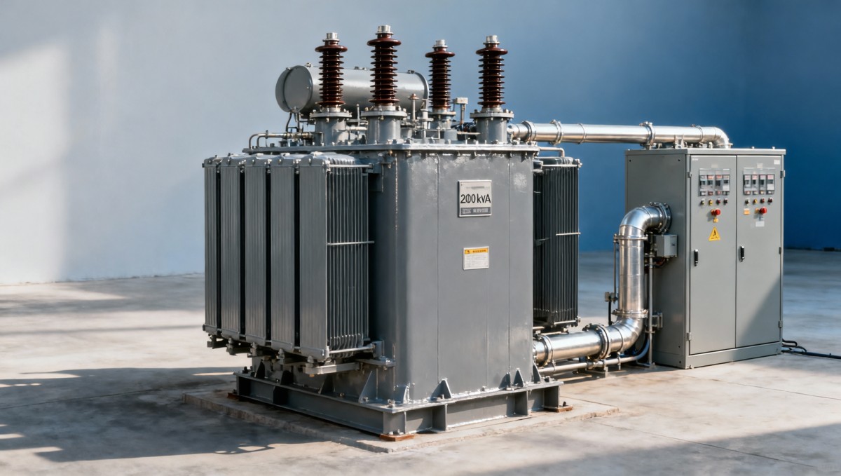
For a 35 kV-to-400 V installation, Jinshida Electric’s 35kV/0.4kV Oil-Immersed Power Distribution Transformer range includes a 2000 kVA option and lists 6.5% short-circuit impedance. Those parameters provide a relevant basis for the 44.4 kA preliminary calculation above. Final coordination should use the impedance specified for the selected unit, its applicable tolerance, and the relevant tap position.
A small impedance change can matter when equipment duty is close to a rating boundary. For example, a hypothetical reduction from 6.5% to 6.0% raises the simplified terminal result from 44.4 kA to 48.1 kA. This comparison illustrates sensitivity; it does not represent a stated manufacturing tolerance.
During procurement, define the required impedance and tolerance alongside voltage, capacity, frequency, and winding connection. Obtain the associated test data for the installed unit. Tap changes can affect the operating voltage and the applicable impedance basis, so a principal-tap calculation should not automatically represent every permitted setting.
Parallel operation adds further requirements. Voltage ratio, tap position, phase displacement, and impedance characteristics affect load sharing and circulating current. The fault study must also include the combined contribution whenever parallel operation is permitted.
What to establish before approving the switchgear
Start with the actual single-line diagram and the permitted operating configurations. Gather utility maximum and minimum fault levels, source X/R data, transformer impedance and tolerance, secondary conductor details, and the fault contribution of other connected sources.
Calculate maximum and minimum currents at the transformer terminals, main switchboard, and relevant downstream boards. Apply the voltage assumptions, correction factors, and equipment comparison rules required by the chosen study method. Then assess breaking, making, and withstand duties together with protection settings.
For a 2000 kVA, 400 V transformer with 6.5% impedance, 44.4 kA is a useful initial reference. Equipment approval depends on the completed circuit model and the duty at each location. Establishing those conditions early gives the transformer specification, switchboard rating, and protection settings a consistent engineering basis.

Get a Quote
Regardless of whether you require general advice or specific support, we are happy to help you.
Send Us Your Inquiry Today

Jinshida Electric remains committed to contributing to global energy development through professional manufacturing and superior service.