





How distribution transformer manufacturers verify winding materials
Distribution transformer manufacturers verify winding materials through a combination of traceable supplier records, conductor identification, dimensional measurements, electrical resistance testing, and insulation checks. No single test is sufficient: a copper-colored surface does not prove a solid copper conductor, and an acceptable finished-transformer resistance result does not establish that every incoming material batch meets specification.
The essential distinction is between verifying the material supplied and verifying the completed winding. Incoming inspection establishes conductor identity, cross-section, condition, and insulation properties. Production and final tests establish whether those materials have been processed into a winding that meets the approved design. Reliable acceptance requires both, with records linking the delivered transformer back to the material lots used.
Acceptance starts with a defined material specification
A purchase order stating only “copper winding wire” or “aluminum strip” leaves critical acceptance questions unresolved. The controlled specification should identify conductor grade, temper, dimensions and tolerances, conductivity or resistivity requirements, surface condition, and applicable insulation requirements. For insulated conductors, it should distinguish bare-metal dimensions from overall insulated dimensions.
Temper matters because winding requires controlled bending and deformation. Material that is too hard can spring back or damage insulation during forming; excessively soft material may deform under winding tension. Correct chemistry alone therefore does not establish suitability.
Copper and aluminum are both legitimate winding materials when the transformer is designed for them. Substitution is not simply a purchasing decision. Their different resistivity, mechanical behavior, joint requirements, and thermal expansion affect conductor sizing and winding construction. Any substitution requires engineering approval rather than acceptance based on apparently similar dimensions.
The specification should also define the inspection unit: a production lot, heat, spool, or foil coil. Without this definition, a passing sample can be incorrectly used to release material from unrelated manufacturing batches.
Certificates must connect to the material actually received
A supplier certificate provides useful evidence only when its identification matches the physical delivery. Inspectors should reconcile the manufacturer, material designation, batch or heat number, spool identification, dimensions, and reported test results against the purchase specification and receiving labels.
A certificate of conformity is not equivalent to a report showing measured values. A statement that material “complies” gives less information than recorded conductivity, tensile properties, elongation, and dimensions with identified test methods. Neither document eliminates the need for independent verification appropriate to the risk.
Traceability must continue after receiving. When a foil coil is slit, a spool is divided, or conductor is issued to several winding jobs, the resulting identifiers should retain the parent-lot connection. Otherwise, an incoming inspection record may be valid but impossible to associate with a completed transformer.
Damaged packaging, missing identification, inconsistent certificate values, or an unapproved manufacturing source justify holding the material. A familiar distributor name does not establish that the underlying conductor producer or manufacturing process remains unchanged.
Confirm conductor identity without overtrusting surface tests
Visual examination can reveal oxidation, contamination, scratches, edge damage, and inconsistent coatings, but it cannot reliably establish bulk composition. Copper-clad aluminum is an obvious example: its surface can appear copper-like while its electrical and mechanical behavior differs from solid copper.
For disputed identity, a prepared cross-section can expose a layered construction. Density measurements can provide supporting evidence when specimen volume and mass are accurately determined and coatings are accounted for. Neither method, by itself, establishes the precise grade or electrical quality of the metal.
X-ray fluorescence can help identify alloying elements and some forms of contamination, but its usefulness depends on the instrument, calibration, specimen geometry, and surface condition. It is primarily a near-surface technique; a coating can make the result unrepresentative of the conductor beneath it. It also does not directly measure conductivity or prove the absence of electrically significant trace impurities.
Where composition must be established more precisely, an appropriate laboratory method, such as optical emission spectroscopy or chemical analysis, should be selected for the metal and required detection limits. The practical rule is to use composition testing to establish identity and grade, then electrical testing to establish the property most directly related to winding losses.
Measure resistance and cross-section together
Conductor resistance depends on resistivity, length, cross-sectional area, and temperature. A resistance result without these supporting measurements can be misleading. A specimen may show excessive resistance because its metal has inadequate conductivity, because it is undersized, or because its temperature was not correctly accounted for.
The governing relationship is:
ρ = R × A ÷ L
Here, ρ is resistivity, R is measured resistance, A is bare-metal cross-sectional area, and L is the measured specimen length. Units must be consistent, and results must be compared at the specified reference temperature.
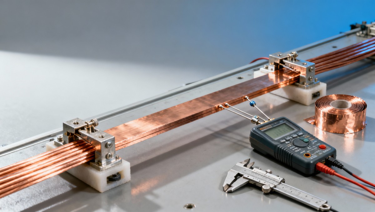
Low-resistance measurements should use a suitable four-terminal, or Kelvin, arrangement to minimize lead and contact resistance effects. Voltage-contact spacing must define the test length. The specimen should reach a stable, known temperature, and measuring current should not introduce significant self-heating.
Temperature correction must use the coefficient applicable to the conductor material and the specified method. Comparing an uncorrected warm specimen with a reference value at 20°C can falsely indicate poor conductivity. Eddy-current conductivity instruments can support screening, but thickness, surface condition, temperature, and calibration affect their suitability, especially for thin conductors.
Dimensional checks should address the actual conductor geometry:
- Round wire: measure bare diameter at multiple positions and orientations to detect undersizing or ovality.
- Rectangular wire: verify width, thickness, and corner geometry; treating rounded corners as sharp corners can overestimate metal area.
- Foil: measure thickness across the width and along the length, rather than relying on a single accessible point.
- Insulated conductors: do not calculate metal area from overall insulated dimensions.
For a fixed material, length, and current, a 5% reduction in conductor area raises resistance and resistive loss by approximately 5.3%. This illustrates why apparently small dimensional deviations can matter even when the conductor composition is correct.
Insulation verification must match the insulation system
“Insulation passed” is incomplete unless the report identifies the material, test method, specimen preparation, conditioning, and acceptance limit. Enamelled wire, paper-covered conductor, and separately applied interlayer insulation have different failure mechanisms and cannot share one generic acceptance test.
For enamelled winding wire, relevant checks can include insulation build, continuity, breakdown voltage, flexibility, adhesion, and resistance to specified thermal or mechanical stresses. A coating can withstand an initial electrical test yet crack during winding if its flexibility or adhesion is inadequate. Testing should therefore reflect the processing stresses imposed by the approved winding method.
Paper-covered conductors require attention to wrapping coverage, overlap, thickness, tears, exposed metal, and contamination. Moisture control also matters for cellulose insulation. Packaging, storage conditions, exposure time, and drying records are part of the evidence; an electrical test alone does not establish that moisture is adequately controlled.
Burrs deserve particular attention on foil and rectangular conductors. A dimensionally acceptable strip can still have an edge capable of cutting adjacent insulation during winding or compression. Edge condition should be assessed against a defined requirement rather than an inspector’s subjective judgment.
Insulation compatibility extends beyond the conductor coating. Paper, enamel, adhesives, insulating liquid, and processing temperatures must belong to an approved insulation system. A higher advertised thermal class for one component does not automatically raise the allowable operating temperature of the transformer.
Which standards apply—and what they do not prove
IEC 60076 provides transformer-level requirements through its applicable parts. For liquid-immersed distribution transformers under an IEEE framework, IEEE C57.12.00 addresses general requirements, while IEEE C57.12.90 provides test procedures. The applicable document, edition, and contractual requirements should be identified before acceptance criteria are established.
These transformer standards should not be treated as complete incoming-material inspection specifications. Finished-unit winding resistance, loss measurements, and dielectric tests provide important evidence, but they do not replace conductor-grade, dimensional, or insulation-material requirements.
For winding wires, the relevant parts of IEC 60317 specify particular wire types, while IEC 60851 addresses winding-wire test methods. Applicability depends on conductor material, shape, insulation construction, and thermal designation. A reference to “IEC 60317 compliant” without the relevant part is insufficient to define the supplied product.
ASTM B193 provides a method for determining the resistivity of electrical conductor materials. It does not, by itself, establish the permitted resistivity, dimensions, or temper for every transformer conductor. Those limits must come from the applicable material specification and approved design.
ISO 9001 certification concerns a quality management system; it is not evidence that an individual spool or transformer has passed its required tests. Likewise, a finished-product approval should not be interpreted as independent certification of every incoming conductor lot.
Carry material verification into winding and final testing
Incoming acceptance cannot prevent defects introduced during production. Winding tension, bending, tooling condition, handling, and joining can damage an otherwise compliant conductor. In-process checks should therefore confirm that insulation remains intact, conductor edges are controlled, and joints follow qualified procedures.
Aluminum connections require particular attention to oxide removal, the approved joining process, and compatibility with connecting materials. A sound conductor batch cannot compensate for an electrically unstable joint. Joint inspection and any specified resistance or mechanical testing should remain distinguishable from bulk-conductor acceptance.
These controls remain relevant when the winding is incorporated into an American-Type Pad-Mounted Substation. Enclosure construction and equipment arrangement do not establish conductor quality; winding-material records must remain traceable to the transformer within the assembly.
Finished winding resistance can help identify connection problems, phase discrepancies, or departures from expected conductor length and area. Interpretation must account for winding temperature, tap position, connection arrangement, and measurement stabilization. Load-loss testing provides further evidence, but measured load loss includes components beyond direct-current conductor loss, so it cannot uniquely establish conductor purity.
A passing dielectric test likewise demonstrates performance under specified test conditions, not the absence of every latent insulation defect. High-voltage testing requires controlled access, suitable interlocks, grounding, and verified discharge procedures; it is not an informal substitute for material inspection.
Release decisions need defined evidence and escalation rules
Inspection frequency should reflect material criticality, supplier history, process changes, and the ability to detect localized defects. A sample can establish the condition of the sampled material; it cannot guarantee that an entire coil has uniform thickness or defect-free insulation. Continuous process records and appropriate production checks are valuable where defects may be intermittent.
When conductivity, dimensions, or insulation results fail, the affected lot should remain segregated while the cause is investigated. Retesting should follow a documented rule, not continue until a passing result appears. Confirming specimen preparation, temperature correction, instrument calibration, and measurement uncertainty helps distinguish a material defect from a testing error.
The release record should identify the specification revision, material lot, sampling basis, actual measurements, instruments, acceptance decision, and any authorized disposition. If suspect material has already entered production, traceability should identify the affected windings and finished units. That connection—not a certificate alone—is what makes winding-material verification an effective safety and quality control.

Get a Quote
Regardless of whether you require general advice or specific support, we are happy to help you.
Send Us Your Inquiry Today

Jinshida Electric remains committed to contributing to global energy development through professional manufacturing and superior service.