





BESS Battery Storage System Failures: Common Causes and Early Warning Signs
Many BESS battery storage system failures begin as small deviations that are easy to dismiss: a cabinet that runs warmer than usual in the afternoon, one rack whose voltage balance drifts after charging, a breaker that trips only during high ramp periods, or a transformer compartment that develops a sharper smell under load. Waiting for a hard shutdown usually turns a manageable defect into cell damage, insulation stress, or wider auxiliary equipment faults. In field practice, the useful approach is to treat minor thermal, electrical, and communication irregularities as linked signals rather than isolated nuisances.
Heat is often the first visible problem, but it is rarely the root cause by itself. In a bess battery storage system, overheating may come from blocked airflow, fan failure, dust buildup on heat exchangers, loose busbar joints, poor cable crimping, cell imbalance, repeated high-current cycling, or ambient conditions outside the original design window. A rack can appear stable at low load and still develop a dangerous hot spot during fast charge or discharge. This is why temperature values from the BMS should be compared with infrared scans at terminals, breaker contacts, fuse holders, cable lugs, and transformer connections instead of being accepted at face value.
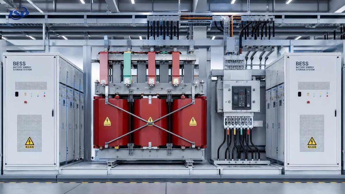
One common misjudgment is to focus only on the battery cabinet while ignoring upstream and downstream interfaces. If a medium-voltage section uses dry-type equipment such as 35kV Three-Phase Cast Resin Dry-Type Distribution Transformer, abnormal heating, harmonic stress, or connection resistance on that side can alter charging behavior and create symptoms that appear to be battery-related. A repeated alarm for DC overcurrent or PCS derating may originate from grid-side instability, poor grounding continuity, or control coordination drift rather than from the cells themselves.
When temperature alarms do not tell the full story
A rising temperature alarm only becomes meaningful after its location and timing are mapped against operating state. If the same module warms during standby, suspect parasitic loss, defective balancing circuitry, or a sensor issue before assuming real thermal runaway risk. If the rise occurs only at the end of charge, investigate overvoltage on specific cells, inconsistent internal resistance, or a cooling response that lags behind the charging profile. When cabinet temperature remains normal but a single terminal is much hotter than surrounding metalwork, the issue is usually contact resistance, oxide film, insufficient torque, or mechanical relaxation after thermal cycling.
Smell matters. A sharp resin odor, heated insulation smell, or faint electrolyte-like note should never be written off as “normal under load.” Cast resin components, cable insulation, and connector housings each age differently under temperature stress. A localized odor near a penetration point or cable bend may indicate excessive bending radius during installation, sheath abrasion during transport, or long-term vibration against enclosure edges. In coastal or chemically aggressive environments, deposits on conductive surfaces can further increase surface leakage and localized heating.
Thermal inspection is most useful when done under repeatable load bands rather than after the system has already tripped. Comparing morning startup, steady midday load, and late-cycle high-temperature conditions often reveals whether the problem is cooling capacity, electrical resistance, or control strategy. A single static thermal image without operating context can be misleading.
Insulation breakdown rarely appears without warning
Insulation problems in BESS installations are not limited to the battery cells. They can develop in DC cables, communication harnesses, auxiliary AC circuits, busbar supports, transformer windings, and termination interfaces. Early warning signs include intermittent insulation monitoring alarms, nuisance trips during humid weather, condensation marks inside cabinets, tracking traces on support surfaces, or a gradual drop in insulation resistance after maintenance work.
Moisture ingress is a repeated trigger, especially where enclosure doors are opened frequently, cable glands are poorly sealed, or temperature swings pull humid air into compartments. Condensation can form on colder metal surfaces first and then migrate to insulating parts. Dust mixed with moisture is more dangerous than either alone because it creates a conductive film that may not cause immediate flashover but can slowly erode dielectric margins. Where cleaning has been performed with unsuitable solvents or excessive pressure, residues may remain in crevices around terminals and sensor blocks, creating a later fault that is difficult to trace back to the intervention.
Insulation testing must also be interpreted carefully. A low reading after shutdown does not always mean material failure; some circuits need time for capacitive discharge and moisture equilibrium before measurement. At the same time, a “pass” value on a dry day should not close the investigation if alarms consistently appear during rain, fog, or overnight cool-down. Trend behavior matters more than one isolated number.
Connection faults often hide behind software alarms
Loose or degraded connections can imitate BMS, PCS, or EMS faults because unstable voltage and current signals propagate through the control system. A slightly loose DC link may cause transient voltage dips, communication resets, or contactor abnormality alarms. Corrosion on low-voltage terminals can interrupt sensor feedback just long enough to generate false high-temperature, fan failure, or isolation fault events. If alarms jump between unrelated subsystems, the investigation should include physical terminations before replacing boards or updating firmware.
Torque records are helpful only when the joint condition has not changed since installation. Aluminum conductors, mixed-metal joints, repeated thermal expansion, and vibration from nearby equipment can alter contact pressure over time. Paint film under a ground lug, incomplete crimp compression, or a washer stack in the wrong order may remain hidden until current rises. On battery racks, inter-module connectors deserve the same attention as main bus connections because small resistance increases can distort module balancing and produce chronic dispatch limitations.
Another field problem comes from transport and lifting. Cabinets that look intact may still suffer shifted brackets, stressed terminals, or hairline damage on support insulators if shock loads were not well controlled. Weeks later, the first symptom may be an intermittent alarm during switching rather than a visible mechanical defect.
Control abnormalities are often coordination problems
Not every control abnormality is caused by a failed controller. In many systems, trouble starts with inconsistent time stamps, unstable communication quality, unverified parameter changes, mismatched firmware behavior between subsystems, or a restart sequence that leaves one device operating with stale limits. A bess battery storage system may continue running in a reduced mode while repeatedly reporting PCS faults, SOC drift, or dispatch refusal, even though the underlying issue is poor handshake between the battery management layer and power conversion controls.
Watch for patterns: alarms that appear after remote parameter adjustment, only during transition between charge and discharge, or only after utility-side disturbances usually point toward control coordination. If contactors close in the correct order but precharge still fails, inspect resistor condition, command timing, feedback latency, and measurement scaling before assuming the contactor itself is bad. If SOC suddenly jumps after communication recovery, compare rack-level data freshness and current sensor calibration. A control room graph may show a software event, but the trigger can still be a drifting shunt, a noisy signal cable, or a grounding reference problem.
Grounding deserves more attention than it often gets. Unequal grounding potential between cabinets, inverter sections, transformer rooms, and monitoring equipment can produce communication instability, erratic sensor values, and unexplained protective action. This becomes more likely after expansion work, cable rerouting, or replacement of metal components with coated parts that interrupt bonding continuity.
Battery symptoms that should be treated early
Cell voltage inconsistency is one of the clearest early warning signs, but it should be judged against operating state and temperature. A small spread at rest may become a larger spread at the top of charge or under discharge peaks. If one module repeatedly reaches limits before the rest of the string, look beyond balancing logic. Internal resistance rise, connector resistance, sensor offset, or uneven thermal conditions may all produce that pattern. Replacing a suspect module without confirming the surrounding electrical path can shift the symptom rather than remove it.
Unusual self-discharge, longer equalization periods, and recurring high-voltage or low-voltage alarms in the same location often suggest developing cell degradation. Mechanical clues matter too: slight panel distortion, vent residue, discolored fasteners, seal changes around module edges, or a cabinet door that no longer closes evenly after heating cycles. None of these alone proves imminent failure, but together they justify a deeper inspection and tighter operational limits until the cause is clear.
Practical inspection points during fault tracing
Sequence matters during troubleshooting. Start with the event record and identify what happened immediately before the first alarm, not just what alarms accumulated afterward. Then compare digital records with physical evidence. A useful path is to verify environmental conditions, inspect ventilation and filter condition, examine mechanical tightness at high-current joints, review insulation behavior, and only then move into board replacement or parameter correction. This reduces the risk of solving the visible alarm while leaving the original fault active.
- Look at whether the fault follows load, ambient temperature, humidity, or switching state. A fault that appears only during transition periods usually points to timing, precharge, or connection issues rather than continuous overload.
- Inspect cable entries, gland sealing, drip paths, and enclosure door gaskets. Water marks, dust lines, or corrosion halos often reveal long-term ingress better than live data does.
- Use thermal imaging on busbars, fuse bases, breaker terminals, transformer terminations, and grounding points under comparable operating current. Relative temperature difference between similar points is usually more informative than a single absolute reading.
- Review maintenance history for recent torque work, firmware changes, sensor replacement, transport, relocation, or cleaning. Many recurring faults start shortly after a well-intended intervention.
Some failures are created by mismatch between components that are individually healthy. Transformer impedance, inverter settings, cable length, grounding practice, and protection thresholds must work together. If one section is modified and the rest of the coordination is left untouched, nuisance trips or accelerated stress can follow. That is why recurring BESS problems should be investigated across the entire power path instead of only inside the battery enclosure.
When warning signs repeat in the same location, the system is already providing a map of where the weak point sits. Treating alarms as isolated events wastes that map. Stable operation usually returns when thermal behavior, insulation condition, connection integrity, and control coordination are checked as one chain rather than four separate topics.

Get a Quote
Regardless of whether you require general advice or specific support, we are happy to help you.
Send Us Your Inquiry Today

Jinshida Electric remains committed to contributing to global energy development through professional manufacturing and superior service.