





What Is a Power Transformer? Key Uses in Industrial and Utility Grid Systems
A maintenance team may first notice the problem as a recurring nuisance rather than a major electrical event: motors hesitate during startup, sensitive controls reset, lights dip when a large load comes online, or a production line must pause after a feeder fault. In a utility setting, the symptom may be a voltage complaint at the edge of a service area or difficulty accommodating a new load connection. The source is not always the transformer, but the transformer is often central to the investigation because it sits between voltage levels and determines how much power can move safely through that part of the network.
This is where a basic question becomes practical: what is a power transformer, and what is it actually doing in an industrial or utility grid system? Understanding its role helps prevent a common mistake—treating every voltage problem as a cable, switchgear, or load issue without checking whether the voltage conversion equipment is correctly rated, configured, cooled, and protected.
The equipment that connects different voltage levels
A power transformer is a static electrical device that transfers alternating-current energy from one circuit to another through electromagnetic induction. Its main job is to change voltage while keeping the electrical frequency unchanged. It may raise voltage for efficient transmission over distance, reduce voltage for use by equipment, or provide electrical isolation between sections of a system.
The basic arrangement includes a magnetic steel core and two or more windings. When alternating current flows through the primary winding, it creates a changing magnetic flux in the core. That flux induces voltage in the secondary winding. The voltage relationship depends largely on the turns ratio between the windings. More turns on the secondary side produce a higher voltage; fewer turns produce a lower voltage.
The process sounds straightforward, but the operating context matters. A transformer must handle the expected load, tolerate switching and lightning-related stresses where applicable, manage heat, and maintain suitable voltage at the receiving end. If any of these conditions are overlooked, a technically correct voltage ratio may still lead to unreliable service.
In everyday discussions, “power transformer” is sometimes used broadly for nearly any transformer in an electrical network. In a stricter utility context, it often refers to larger units used in generation stations, transmission networks, and substations. Distribution transformers are generally the final voltage-reduction stage before electricity reaches facilities or local users. Both rely on the same electromagnetic principle, but their installation conditions, capacities, voltage classes, and operating priorities can differ significantly.
Why voltage must change before power travels or reaches equipment
Electricity sent over long distances at a low voltage requires higher current for the same amount of power. Higher current increases conductor losses and can demand larger cables or overhead conductors. Utilities therefore use step-up transformer stages near generation sources to raise voltage before transmission. At substations, other transformers progressively reduce that voltage for regional distribution networks.
By the time electricity reaches an industrial plant, commercial building, hospital, or infrastructure project, the incoming supply may still be much higher than the voltage needed by motors, lighting, control panels, and general low-voltage distribution boards. A step-down transformer bridges that gap.
For example, a site supplied at medium voltage may need a transformer that converts the incoming level to 0.4 kV for low-voltage loads. This arrangement allows the site to receive power at a practical distribution voltage while operating equipment designed for its local low-voltage system. It also gives designers a controlled point for protection coordination, metering, grounding decisions, and future load planning.
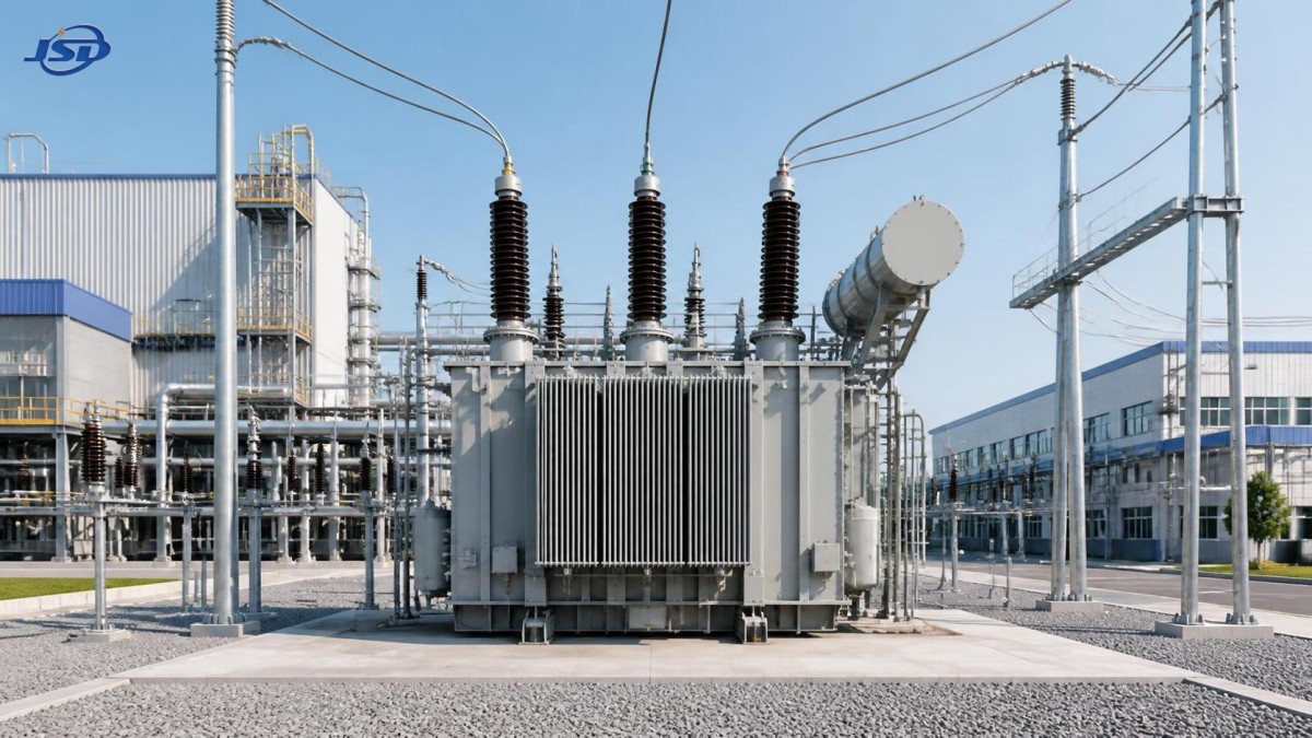
Where transformer selection becomes a real operational issue
In an industrial facility, transformer decisions usually surface when a plant is expanding, replacing aging electrical equipment, adding variable-speed drives, or installing a high-demand process line. The first temptation is to select a unit based only on present connected load. That approach can be risky because connected load is not the same as simultaneous demand, and demand is not the same as a transformer’s thermal duty under the actual ambient conditions.
Consider a plant with large motors. During starting, some motor arrangements can create substantial temporary current demand. If the transformer, upstream feeder, and protection settings have not been evaluated together, voltage dip may interfere with controls or other equipment. Conversely, selecting an excessively large unit without considering operating load can raise unnecessary no-load losses and equipment cost. The appropriate choice depends on the site’s load profile, starting method, power factor, harmonic content, planned growth, and ventilation conditions—not just a nameplate number.
Utility systems face a related but broader challenge. A transformer may need to serve seasonal demand changes, distributed renewable generation, feeder reconfiguration, or a growing customer base. Voltage regulation and tap settings become important because a satisfactory voltage at one load level may not remain satisfactory when the network condition changes. The power transformer is therefore part of a larger system rather than an isolated purchase.
Common misunderstandings that lead to poor decisions
“A transformer creates power.”
It does not. A transformer transfers electrical energy between circuits and changes voltage and current in proportion to its winding ratio. There are losses in the core and windings, so the output power is slightly lower than the input power. The purpose is efficient and usable delivery, not power generation.
“The kVA rating tells me everything.”
Capacity is essential, but it is only one part of the decision. A suitable unit must also match primary and secondary voltage, frequency, connection or vector group where relevant, impedance, insulation class, cooling method, installation environment, and applicable project requirements. Two transformers with the same kVA rating may behave differently within the same network because their impedance and configuration affect fault current and parallel operation.
“Dry-type and liquid-filled units are interchangeable.”
They perform the same fundamental electrical function, but their cooling media, installation needs, fire considerations, maintenance practices, and environmental constraints differ. Liquid-filled units are widely used in many outdoor and high-capacity applications. Dry-type transformers are often considered where indoor installation, fire performance, reduced fluid-related concerns, or space conditions influence the design. The final choice should be based on the project’s electrical design and local requirements rather than a general preference.
“If voltage is wrong, the transformer must be faulty.”
Voltage issues can arise from feeder length, conductor sizing, poor connections, excessive load, incorrect tap position, upstream supply variation, harmonic distortion, or protection and control problems. A transformer should be checked, but replacing it before identifying the cause can waste time and leave the real fault untouched.
A practical way to assess the application
Start with the source and load sides. Record the actual or specified incoming voltage, the required outgoing voltage, system frequency, earthing arrangement, and expected load type. These details establish whether the transformer’s basic electrical configuration is suitable.
Next, examine the load pattern. Does the site run at a fairly stable load, or does it cycle between light operation and sharp peaks? Are there large motors, welding equipment, rectifiers, UPS systems, drives, or charging equipment? Nonlinear loads can introduce harmonics that increase heating in windings and associated conductors. A transformer selected for ordinary linear loads may need additional evaluation when the load includes a significant amount of power electronic equipment.
Then look at the physical location. Indoor transformer rooms, basements, rooftops, dusty workshops, mining environments, and renewable-energy substations create different demands. Ventilation, ambient temperature, clearance, moisture, access for inspection, noise limits, and fire-safety provisions should be considered before the equipment arrives on site. These details are often discovered too late, when a unit has already been specified but cable routing, room airflow, or handling access remains unresolved.
Protection coordination is another important step. Fuses, circuit breakers, relays, surge protection, and downstream protective devices must work together. Transformer impedance influences available fault current, while inrush current can affect energization behavior. The settings should be developed by qualified electrical engineers using the actual system information. It is not enough to copy settings from a different facility with a similar transformer rating.
One distribution-level option for medium-voltage sites
Where a project needs to step a 10 kV supply down to 0.4 kV, a cast-resin dry-type distribution design may be considered when its installation characteristics fit the project. The 10kV Cast Resin Dry-Type Distribution Transformer is specified for step-down transformation from 10 kV to 0.4 kV and is available across a 30–2500 kVA capacity range. Such a range can be relevant for facilities with different distribution demands, from smaller building services to larger plant sections.
Its listed construction includes a core made from cold-rolled grain-oriented silicon steel sheet, high-voltage copper strip winding, low-voltage copper foil winding, and resin-based insulation materials. In practical terms, these construction details relate to electrical performance, mechanical strength, insulation integrity, and heat management, but they do not remove the need to verify the entire installation design.
For projects where continuity planning is important, the stated temperature protection and control system and forced-air operating provision should be reviewed alongside the site’s ventilation design and operating rules. The product information also lists high-voltage tapping options, while voltage, capacity, frequency, vector group, and losses can be customized. Those choices should be confirmed early, especially if the incoming utility voltage is not exactly the same as the nominal project assumption.
Signs that deserve professional investigation
Some transformer conditions should not be handled as routine operating adjustments. Repeated protective trips, unexplained overheating, unusual humming that changes abruptly, visible insulation damage, persistent odor, loose or discolored terminals, or evidence of moisture require prompt assessment by qualified personnel. For a dry-type unit, blocked ventilation paths and accumulated dust can also contribute to elevated temperature, particularly in industrial environments.
Voltage imbalance downstream may indicate uneven loading, poor connections, supply-side issues, or a problem in the transformer or connected conductors. Before drawing conclusions, measurements should be taken with appropriate instruments and safe procedures. Comparing phase voltages, load current, temperature indications, and the condition of connections can narrow the investigation. Electrical isolation, testing, repair, and protective-setting changes must follow authorized work practices.
Keeping the transformer from becoming the forgotten part of the system
A power transformer often works quietly for long periods, which is why it can be neglected until a problem becomes disruptive. A better approach is to include it in normal electrical maintenance planning. Keep ventilation areas clear, inspect accessible connections during scheduled shutdowns, review loading when new equipment is added, and investigate repeated alarms rather than merely resetting them. When facility loads change, revisit the transformer’s duty instead of assuming the original selection still fits.
The central idea is simple: a transformer is not merely a voltage-changing box. It is a designed link between supply conditions and real operating loads. When voltage ratio, capacity, cooling, protection, installation environment, and future demand are considered together, it can support stable distribution in utility networks, industrial facilities, renewable-energy systems, and critical buildings. When those factors are treated separately, even a correctly rated transformer can become the weak point in an otherwise capable electrical system.

Get a Quote
Regardless of whether you require general advice or specific support, we are happy to help you.
Send Us Your Inquiry Today

Jinshida Electric remains committed to contributing to global energy development through professional manufacturing and superior service.