





Evaluating Lifecycle Cost of High-Capacity Substation Transformer Upgrades
The purchase price of a high capacity substation transformer is only the most visible part of the upgrade cost. It can also be the least useful number when comparing two proposals. A lower initial quotation may carry higher energy losses, more demanding maintenance, a longer installation outage, or a greater risk of expensive service disruption later.
A sound lifecycle-cost decision asks a different question: which option delivers the required capacity and reliability at the lowest total cost over its useful operating life? That means assessing the transformer, its installation, its expected loading pattern, and the consequences of failure as one investment rather than separate technical and budget items.
This approach is especially important when an existing unit is near its thermal limit, load growth is uncertain, or the site supplies processes that cannot tolerate a prolonged interruption. In those conditions, the “cheapest transformer” and the “lowest-cost upgrade” are often not the same choice.
Start with the cost categories that actually change the decision
Lifecycle cost should include more than equipment supply. Some costs are paid once, some recur every hour the transformer is energized, and some appear only when a fault or installation delay occurs. Treating all of them as part of the approval case makes competing offers easier to compare on a like-for-like basis.
The appropriate analysis period should match the organization’s normal asset-planning horizon. It is less important to predict every future cost perfectly than to use the same assumptions for each option. Energy price, annual operating hours, expected load profile, planned expansion, outage value, and discount method should be consistent across all supplier comparisons.
Energy losses deserve more attention than nameplate capacity alone
Transformer losses are often described in two parts. No-load loss, sometimes called core loss, is present whenever the transformer is energized, even when little power is being delivered. Load loss, mainly associated with current flowing through windings and other components, increases as loading rises.
This distinction matters because two sites with the same rated capacity may have very different cost priorities. A transformer that remains energized around the clock but runs lightly loaded for long periods is more sensitive to no-load loss. A unit serving a heavily utilized industrial process, data-intensive facility, or large charging load is more affected by load loss. A supplier’s loss figures should therefore be evaluated against the site’s actual or forecast load curve, not against a generic “average loading” assumption.
Oversizing can be justified, but it is not automatically economical. It may provide thermal margin, accommodate expansion, or improve operational resilience. Yet a larger unit can impose a higher capital cost and may increase the cost of losses when demand growth does not arrive. The better question is not “how much spare capacity can we buy?” but “what load growth is sufficiently likely, and what is the cost of serving it through this asset?”
Request guaranteed loss values at the specified voltage, frequency, cooling arrangement, and tapping condition. Do not compare a guaranteed figure in one proposal with a typical figure in another. The calculation should also state whether auxiliary cooling equipment is expected to run regularly, because that affects both electricity use and maintenance.
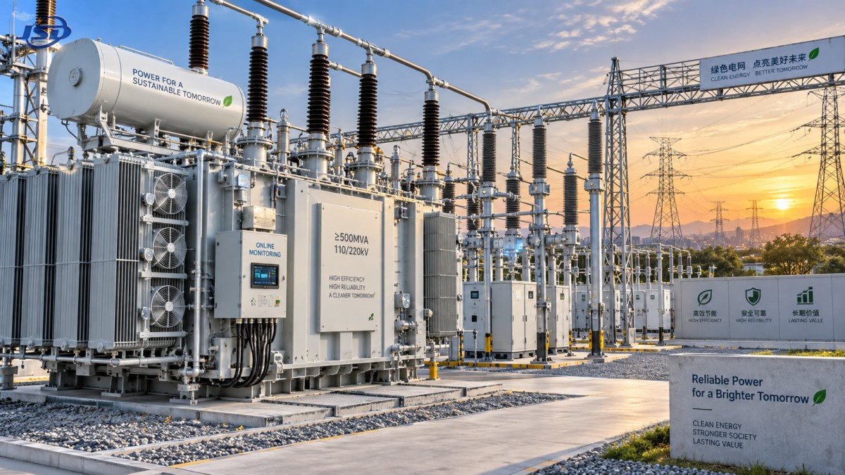
Capacity margin should reflect the load, not a rule of thumb
High-capacity upgrades are frequently approved after a plant expansion, a new renewable interconnection, additional urban load, or repeated overload alarms. Those triggers do not always mean that a single larger transformer is the right answer.
A single high capacity substation transformer can simplify the footprint and may reduce some installation interfaces. However, it concentrates more load into one asset. If that asset is unavailable, the operational consequence can be substantial unless there is alternate supply capacity. Parallel transformers, sectionalized bus arrangements, or staged upgrades may cost more initially but can provide operational continuity and a better path for phased demand growth.
The choice depends on the value of resilience at that site. A facility with flexible production scheduling may accept a simpler single-unit arrangement. A site with continuous processes, safety-critical systems, or contractual availability requirements may place a much higher value on redundancy. That value belongs in the lifecycle model; it should not be left as an unpriced engineering preference.
Do not model overload capability as permanent capacity
Some transformer designs can support short-duration or controlled overload operation when cooling and temperature protection are properly arranged. This can be useful for peak management or contingency conditions. It should not be used to justify a design that will operate above its intended duty for normal daily demand.
Repeated high loading affects thermal stress, insulation ageing, cooling demand, and the margin available during unusual ambient conditions. A business case that relies on overload operation should separately show normal loading, expected peak duration, cooling requirements, and the consequence if one supporting system is unavailable.
Installation scope can reverse an apparently favorable quotation
Before approval, map the physical and electrical interfaces of the upgrade. This step often identifies costs that are not clear in an equipment quotation: transformer delivery route, lifting access, indoor room dimensions, ventilation, fire separation, cable termination changes, protection coordination, earthing upgrades, switchgear ratings, and outage sequencing.
Oil-filled and dry-type transformers can create materially different project scopes. Where installation is inside a building or close to occupied areas, fire performance, containment requirements, ventilation arrangements, and maintenance access can affect total installed cost. A dry-type design may reduce concerns associated with insulating liquid and oil leakage, but it still needs suitable ventilation, environmental protection, and access for inspection. The correct comparison is site-specific rather than a blanket preference for one technology.
For example, an 11 kV distribution upgrade serving an indoor industrial or civil-building network may warrant consideration of a cast-resin unit such as the 11kV Three-Phase Cast Resin Dry-Type Distribution Transformer. Its available range extends to 2500 kVA, and its non-flammable epoxy-resin insulation can be relevant where indoor fire performance and reduced oil-related maintenance are part of the project criteria. That does not make it a substitute for a larger transmission-class transformer; it is a fit to assess where voltage level, capacity, installation environment, and distribution duty align.
Reliability is a financial input, not a vague quality claim
Reliability is difficult to reduce to one universal number because it depends on design, manufacturing control, protection settings, loading, ambient conditions, maintenance practice, and the quality of installation. It can still be assessed in a disciplined way.
Review the supplier’s technical documentation for insulation system, winding construction, cooling method, temperature monitoring, protection interfaces, routine and type-test evidence relevant to the specified design, and quality controls. Then focus on recovery: availability of technical support, clarity of warranty responsibilities, access to spares, response arrangements, and lead time for a replacement unit. These are commercial issues with direct cost consequences when an unexpected failure occurs.
It is also important to separate transformer risk from system risk. A high-quality unit cannot compensate for inadequate surge protection, poorly coordinated protection relays, restricted ventilation, harmonics beyond the design assumption, or weak maintenance of upstream and downstream equipment. The approval package should show how these site conditions have been addressed.
Maintenance economics depend on location and operating discipline
Maintenance should be evaluated as a combination of scheduled work, access requirements, condition monitoring, and the likelihood that small issues become outages. An outdoor substation with good access may tolerate a different maintenance strategy from an indoor transformer room with restricted shutdown windows.
Dry-type transformers generally avoid oil sampling, oil treatment, and leakage management. In dusty, humid, corrosive, or poorly ventilated areas, however, inspection and cleaning remain important. Cooling passages, terminations, enclosure condition, temperature sensors, and signs of abnormal heating all need regular attention. Reduced routine maintenance does not mean no maintenance.
For liquid-filled designs, fluid condition and leak management are more prominent parts of the maintenance plan. Those added tasks may be entirely acceptable where the installation is outdoors, space is available, and the chosen design offers a strong economic fit. The decision should be based on the whole site requirement, including fire and environmental controls, rather than maintenance cost alone.
Build the approval case around scenarios, not one forecast
A single forecast creates false precision. A more practical approval model tests a base case, a slower-growth case, and a higher-demand case. It can also test an energy-price change, a delayed expansion, and an outage event for critical operations. The purpose is not to prove that one option always wins. It is to reveal which assumptions drive the result and whether the preferred option remains acceptable when conditions change.
For each candidate, calculate total installed cost, annual loss cost under each load scenario, planned maintenance cost, and the expected financial exposure of a prolonged outage. Present the result with the assumptions visible. This makes it easier to distinguish a proposal that is economically robust from one that only appears attractive under optimistic loading or energy assumptions.
Pay particular attention to the cost of deferring the upgrade. Keeping an ageing transformer in service may preserve cash in the short term, but recurring overload restrictions, rising repair exposure, limited spare capacity, and an unplanned replacement can make deferral more expensive than a controlled project. Conversely, replacement should not be accelerated merely because a newer model is available. The trigger should be a defensible combination of condition, capacity need, loss economics, safety requirements, and outage risk.
Questions that should be answered before approval
- What load profile, peak demand, power factor, harmonic content, and growth assumptions were used to size the transformer?
- Are no-load and load losses guaranteed for the proposed design, and have they been costed using the same operating assumptions for every bid?
- What site modifications are included in the quoted scope, and which are excluded?
- Does the preferred arrangement provide acceptable continuity of supply during maintenance or an equipment failure?
- What monitoring, protection, cooling, inspection, and service support are required for normal operation?
- Can the selected unit be transported, installed, replaced, and maintained within the physical constraints of the site?
Suppliers should be asked to respond to these points in a common technical-commercial format. Jinshida Electric Power Technology Co., Ltd. supports transmission and distribution projects with an emphasis on manufacturing quality, energy-efficient equipment, and application-specific technical support. For a lifecycle comparison, the useful contribution from any supplier is not only a price sheet, but a clear definition of design assumptions, losses, included scope, and operating requirements.
The strongest upgrade decision is usually the one that makes its trade-offs explicit. It may cost more at purchase because it reduces energy use, limits outage exposure, fits the installation without major reconstruction, or preserves room for credible future demand. Or it may favor a simpler design because the load is stable, backup supply exists, and the added resilience would not justify its cost. In either case, lifecycle cost turns the discussion from “which transformer is cheaper?” into “which investment is least costly to own and operate for this specific system?”

Get a Quote
Regardless of whether you require general advice or specific support, we are happy to help you.
Send Us Your Inquiry Today

Jinshida Electric remains committed to contributing to global energy development through professional manufacturing and superior service.