





When Does a High-Voltage Transformer Need an On-Load Tap Changer?
A high voltage transformer with tap changer becomes necessary when the transformer must do more than convert voltage at a fixed ratio. In many real distribution systems, the incoming voltage changes with load, feeder length, generator output, or switching conditions. If the secondary voltage must remain within a usable band while those conditions move, an on-load tap changer (OLTC) may be the right tool.
The key phrase is while energized. An OLTC changes the transformer ratio without interrupting the load. That distinction matters in substations, process plants, renewable interconnection points, hospitals, and other installations where a brief outage is not merely inconvenient. It can trip drives, disrupt production, reset control systems, or force sensitive equipment onto backup power.
The practical difference between off-circuit taps and OLTCs
Most power transformers have some form of tap adjustment. A no-load or off-circuit tap changer is relatively simple: the transformer is de-energized, isolated, and then manually moved to another tap position. This works well where supply voltage is broadly stable and adjustments are occasional, such as seasonal commissioning changes or a long-term correction after a feeder is reconfigured.
An OLTC is different because it is designed to make those ratio changes under load. Its switching mechanism transfers current from one tap to another through a controlled sequence, avoiding an open circuit or unacceptable short circuit between taps. The arrangement is more complex, usually more expensive, and requires a more deliberate maintenance strategy. For that reason, specifying an OLTC simply because “voltage regulation is good” is not sound engineering. The question is whether voltage changes are frequent enough, consequential enough, and unpredictable enough to justify it.
In practice, the automatic voltage regulator monitors a selected voltage point and commands tap operations when the measured voltage stays outside a deadband for a defined time. Proper settings are important. A controller that reacts too quickly can hunt between taps during normal fluctuations; one with a wide deadband may allow customer voltage to drift further than the connected equipment can tolerate.
Situations where on-load regulation is usually justified
The strongest case for an OLTC is not a single voltage dip. It is a recurring operating condition that cannot be handled reliably by fixed taps, feeder reinforcement, local reactive compensation, or downstream equipment tolerance.
Long feeders with changing load profiles
A substation feeding a long urban, rural, or industrial feeder can see materially different voltage conditions at light load and peak load. Voltage drop rises as current increases, particularly where the feeder is long or has substantial reactive demand. Setting a fixed tap for the peak may leave voltage unnecessarily high during low-load hours. Setting it for normal load may leave the remote end low during evening demand or heavy production periods.
An OLTC allows the transformer to compensate for these system-level shifts. It does not eliminate voltage drop along the feeder, but it can keep the transformer bus voltage in a controlled range and give the network more room to meet its voltage target at the receiving end.
Grid supply points with variable upstream voltage
Transmission and subtransmission voltage is not perfectly constant. It can change with network loading, transformer switching, reactive-power flows, and operating arrangements elsewhere on the grid. At a primary distribution substation, these movements may be passed directly into the medium-voltage network unless the transformer ratio is adjusted.
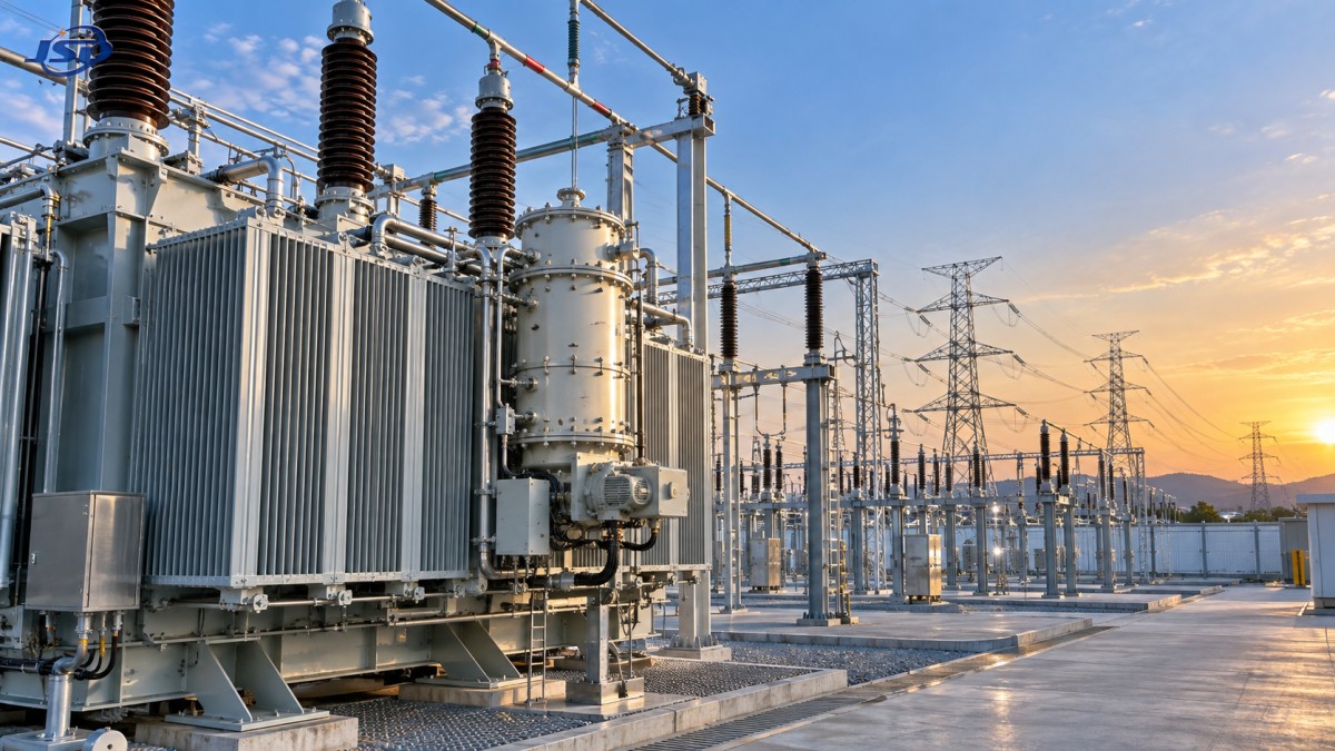
This is a familiar OLTC application: a high-voltage-to-medium-voltage transformer maintains a prescribed bus voltage despite normal upstream variation. The design should be coordinated with utility voltage-control philosophy, capacitor banks, reactors, and any adjacent transformers operating in parallel. An OLTC that acts independently in a parallel-transformer bank can create circulating current and unnecessary tap operations.
Industrial facilities where process equipment is voltage-sensitive
Large motors, variable-frequency drives, rectifiers, furnaces, compressors, and automated production lines can make a plant’s voltage profile far less predictable than its nameplate demand suggests. Starting currents and cycling loads are one issue; sustained changes in load are another. An OLTC is not intended to correct every fast transient, but it can manage slower voltage movement caused by changing operating states.
This is where project teams should avoid a common mistake: treating the OLTC as a cure for poor power quality in general. Fast voltage flicker, harmonics, unbalance, and deep short-duration sags may require different measures. Harmonic studies, power-factor correction design, dynamic reactive support, or equipment-level ride-through capability may be more relevant. The OLTC is a voltage-ratio control device, not a universal power-quality device.
Renewable energy connections with reverse or changing power flow
Wind and solar projects have changed how many distribution networks behave. A feeder that historically carried power one way may experience reverse power flow when generation is high and local demand is low. Voltage may rise near the point of connection, then fall again as generation declines. The effect depends on conductor impedance, plant output, local demand, reactive-power controls, and utility operating rules.
A high voltage transformer with tap changer can be valuable at a renewable interconnection point, but the control scheme must be studied rather than copied from a conventional load substation. The regulator may need line-drop compensation, reverse-power logic, voltage-reactive control coordination, or remote setpoint capability. Without that coordination, tap changes can conflict with inverter controls and produce more movement than the system actually needs.
When an OLTC may be the wrong choice
Not every transformer that has taps needs an on-load tap changer. For a compact distribution transformer serving a stable local load, fixed off-circuit taps are often the sensible solution. They cost less, have fewer moving parts, and avoid the maintenance burden associated with a motor drive and diverter-switch assembly.
A transformer dedicated to one facility with a stable incoming supply and predictable load may only need a commissioning tap selection. The same can apply to many low-voltage distribution points. For example, a 15kV/0.4kV Oil-Immersed Power Distribution Transformer used for local conversion from a 15 kV network to 0.4 kV, 0.415 kV, or 0.420 kV should be evaluated according to the actual voltage variation at that point, not assumed to need OLTC capability because it serves a critical-looking site.
For hospitals, data centers, mines, petrochemical plants, and public facilities, reliability requirements can be high. Yet reliability does not automatically mean on-load regulation at every transformer. A layered design may instead use upstream voltage control, redundant transformer capacity, UPS systems, standby generation, or static voltage-support equipment. The right choice depends on where voltage instability originates and how quickly it changes.
Questions that should be answered before specifying one
An OLTC decision should begin with measured or modeled operating conditions, not a generic equipment preference. Engineers normally need to examine the expected high-side voltage range, the required low-side voltage band, maximum and minimum load, feeder impedance, power factor, and projected changes in generation or demand. If the network will operate transformers in parallel, vector group, impedance, tap range, tap step, and control interlocking also need attention.
- How far does the incoming voltage move during normal operation, not just during faults?
- Does the load change gradually over minutes or hours, or does it fluctuate too quickly for tap control to follow?
- What voltage range can downstream motors, drives, converters, and protection systems accept?
- Could capacitor banks, feeder upgrades, inverter VAR control, or a fixed tap solve the issue at lower lifecycle cost?
- Who will inspect, test, and maintain the OLTC mechanism over the transformer’s service life?
That final question is routinely underestimated. OLTCs are durable when properly selected and maintained, but they are mechanical switching systems operating in oil or vacuum-based arrangements depending on design. Contact wear, oil condition where applicable, drive mechanism condition, control wiring, operation counters, and motor-drive performance all deserve attention. A site that cannot support planned maintenance may be better served by a simpler transformer arrangement and a different voltage-control approach.
Transformer size and voltage control are related—but not interchangeable
Capacity selection is often discussed alongside voltage regulation, but the two decisions solve different problems. A larger transformer may reduce loading and improve voltage drop within the transformer itself, yet it does not automatically correct voltage changes caused by the upstream grid or a long downstream feeder. Conversely, an OLTC can regulate ratio but cannot make up for inadequate capacity, excessive conductor losses, or poor thermal design.
For oil-immersed distribution equipment in the 30–5000 kVA range, designers should look at loading duty, cooling conditions, fault level, space, and maintenance access as well as nominal voltage. Where copper-wound 15 kV transformers are expected to carry short-duration overloads, operating limits must be tied to thermal monitoring rather than treated as extra everyday capacity. For the referenced distribution design, short-term loading up to 150% of rated capacity for no more than two hours requires oil temperature monitoring and a limit of 95°C. That is an operational allowance, not a substitute for proper demand planning.
Installation details also affect long-term reliability. Adequate clearance supports cooling, inspection, and safe access; an indicated minimum of 1.5 meters from the wall should still be checked against the specific installation layout and applicable local requirements. In locations where fire risk or environmental considerations influence the design, FR3 vegetable oil may be considered, subject to the project’s insulation, fire-safety, and approval requirements.
A useful rule of thumb
Specify an OLTC when the system needs repeated, automatic voltage correction under energized conditions and the consequences of voltage drift are meaningful. This commonly points toward grid substations, major industrial supplies, renewable-energy interfaces, and infrastructure networks with variable load or source conditions.
Choose fixed taps when voltage is stable, adjustments are rare, and simplicity is worth more than continuous regulation. The most reliable arrangement is not necessarily the one with the most controls. It is the one whose transformer design, tap range, control logic, protection, and maintenance plan match the way the electrical system will actually operate. Manufacturers such as Jinshida Electric Power Technology Co., Ltd. can support that evaluation by aligning transformer configuration with grid, industrial, new-energy, and infrastructure duty rather than treating every voltage-conversion project as the same.

Get a Quote
Regardless of whether you require general advice or specific support, we are happy to help you.
Send Us Your Inquiry Today

Jinshida Electric remains committed to contributing to global energy development through professional manufacturing and superior service.