





How Transformer Losses Affect Energy Yield in Solar Power Plant Projects
Transformer losses are a yield issue, not just an equipment efficiency figure
In a solar power plant, every kilowatt-hour lost between the inverter output and the grid revenue meter reduces the energy available for sale. Transformer losses therefore affect more than the electrical design calculation: they influence annual energy yield, project financial modelling, equipment sizing, heat management, and the credibility of generation guarantees.
For a utility-scale project, a high voltage transformer for solar power plants should be evaluated as part of the plant's energy-conversion chain. A transformer with a lower purchase price can create a larger lifetime cost if its no-load losses remain high throughout daylight hours, or if its load losses rise sharply during the periods when the plant produces its most valuable output. The financial consequence may be modest for one unit, but it becomes material when repeated across many inverter stations or compact substations.
The practical question for developers and EPC buyers is not simply whether one transformer has a higher efficiency percentage than another. It is whether its loss profile matches the solar plant's expected loading curve, operating temperature, connection arrangement, and commercial energy model.
How transformer losses reduce saleable solar energy
Transformer losses are generally divided into no-load losses and load losses. Both consume energy that would otherwise move toward the point of grid connection, but they behave differently and should not be assessed in the same way.
No-load losses, often associated with the transformer core, occur whenever the transformer is energized. They are relatively stable regardless of whether the PV plant is producing at low output or close to full capacity. In solar applications, these losses are particularly relevant because transformers may remain energized for long periods while production varies substantially during the day and falls to zero at night.
Load losses arise mainly in the windings and other current-carrying parts. They increase as loading rises, approximately in relation to the square of current. A transformer that performs acceptably at a moderate loading point may lose considerably more power near its peak operating range. This matters in PV facilities because a large share of annual generation can be concentrated in fewer high-irradiance hours.
The total impact is best understood through the plant's actual operating profile. A project with low average loading but long energization hours may place more value on minimizing no-load loss. A site that frequently operates near inverter export capacity may gain more from reducing load losses and avoiding unnecessary temperature rise. Neither design objective can be selected correctly from nameplate capacity alone.
Losses also have a compounding effect. Electrical energy is lost directly, while the heat created by those losses adds thermal stress to insulation, terminals, bushings, cable interfaces, and enclosure ventilation systems. Higher operating temperature can restrict useful capacity, accelerate insulation ageing, and make performance less stable in hot climates. The yield model should account for the energy loss; equipment selection must also account for the operating conditions that make that loss harder to manage.
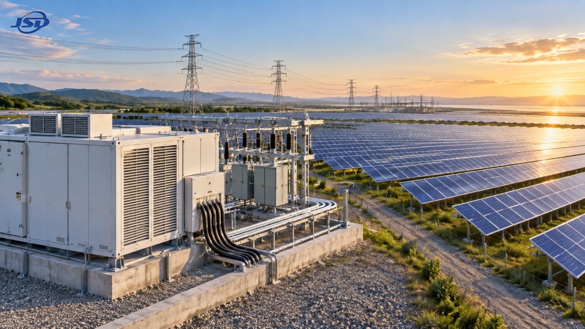
A high efficiency rating can still be the wrong procurement choice
Efficiency values are often quoted at a specified load point, such as 50%, 75%, or full load. That figure is useful, but it does not answer how the transformer will behave across a solar plant's full annual profile. Two units may show similar rated efficiency while having different balances of core loss and winding loss. One may be more appropriate for a plant with substantial morning and afternoon operation; the other may be better suited to a site where equipment is consistently pushed closer to rated output.
Buyers should ask suppliers to state guaranteed no-load loss, load loss at the stated reference temperature, impedance, tap range, and the assumptions used for the quoted efficiency. These values should be reviewed alongside hourly or interval-based generation modelling where available. A simple comparison at one nominal load condition can obscure the more important annual-loss difference.
It is also important to distinguish transformer capacity from the plant's likely electrical loading. Oversizing can lower load losses during peak production, but it may introduce higher no-load losses and additional capital cost. Undersizing can produce high copper losses, excessive heat, and limited headroom for inverter clipping strategies, reactive-power obligations, or later plant expansion.
The appropriate rating depends on several project-specific factors:
- DC/AC ratio and anticipated inverter clipping behavior;
- the number, output rating, and diversity of inverter blocks connected to each transformer;
- ambient temperature, solar gain on enclosures, altitude, dust, and ventilation conditions;
- grid-code requirements for reactive power and voltage support;
- expected curtailment, export limitations, and battery integration plans;
- the commercial value assigned to energy during high-production periods.
For example, an AC-side transformer selected only around a nominal inverter output may have limited margin when the grid operator calls for reactive power support. Reactive current contributes to loading and loss even when active solar export is constrained. A design that appears efficient in a simplified active-power calculation can then operate at a less favorable thermal point.
The loss calculation should follow the plant layout
Transformer-loss evaluation should begin with the electrical architecture, because loss allocation changes with voltage level and equipment location. A centralized arrangement with fewer larger transformers has a different loss pattern from a distributed architecture using multiple inverter-transformer stations. There is no universal winner. Fewer larger units may reduce duplicated no-load losses, while distributed units can shorten low-voltage cable runs and reduce losses elsewhere in the collection system.
That tradeoff is frequently missed when transformer bids are reviewed separately from cable and substation design. Moving voltage transformation closer to the inverter may reduce low-voltage current paths, but it adds more energized transformer cores across the site. Combining blocks into a larger collection transformer can reduce the number of cores, though cable routing, fault isolation, access, and construction logistics may become more difficult.
The decision should therefore compare system losses rather than transformer losses in isolation. At minimum, the project team should evaluate:
- inverter output voltage and transformer low-voltage winding voltage;
- cable lengths and conductor sizes on both sides of each transformer;
- medium-voltage collection voltage and the distance to the main step-up transformer;
- transformer impedance and its effect on voltage regulation, parallel operation, and fault studies;
- auxiliary consumption for cooling, ventilation, monitoring, and enclosure environmental control;
- the consequences of one unit being unavailable for energy production and grid compliance.
This is why a low-loss transformer alone does not guarantee the lowest project loss. A slightly higher-loss unit placed in a more suitable electrical layout may deliver a better whole-plant result than a technically superior unit installed with long, heavily loaded low-voltage cables. Procurement teams should require an integrated loss schedule from the EPC contractor or electrical designer, with losses separated by inverter, cable, transformer, switchgear, and auxiliary system where practical.
Operating conditions can erase paper efficiency advantages
Nameplate loss guarantees are typically tied to defined test conditions. Solar sites can depart materially from those conditions. High ambient temperatures raise conductor resistance. Enclosures exposed to direct solar radiation may retain heat. Dust, salt mist, humidity, and poor airflow can degrade thermal performance or raise maintenance requirements. High altitude changes cooling capability. Harmonic content from inverters can add losses beyond a conventional sinusoidal loading assumption.
These conditions do not make published transformer data irrelevant; they make the application review more important. The buyer should confirm whether the transformer is designed for the actual ambient temperature range, altitude, installation type, and waveform environment. Thermal margins should be reviewed with the enclosure, cables, switchgear, and ventilation arrangement considered together.
For distributed solar blocks, the compact-substation enclosure deserves the same scrutiny as the transformer itself. A fully enclosed arrangement can improve safety and reduce exposure to dust and moisture, but the enclosure must still dissipate heat adequately at the intended duty. In renewable-energy projects using an integrated MV/LV arrangement, an European-Type Compact Substation can be configured with transformer capacities from 100kVA to 2500kVA, with options for outdoor materials and protection levels. That configuration flexibility is useful only when thermal design, transformer losses, switchgear duty, and site environment are reviewed as one package.
Harmonics require particular attention. Inverter-based generation can introduce non-sinusoidal current components, and their effect on losses depends on transformer construction and the actual harmonic spectrum. A standard loss figure may not represent additional eddy-current and stray losses under harmonic loading. Where the inverter manufacturer provides harmonic data, it should be included in the transformer supplier's application assessment rather than left as a generic specification note.
How to compare lifecycle cost without relying on a single price number
Capital cost remains important, but a meaningful bid comparison should translate guaranteed losses into expected operating cost over the project evaluation period. The calculation does not need to pretend that future irradiation, tariffs, curtailment, and degradation can be predicted perfectly. It should use consistent assumptions across bids so that the tradeoff is visible.
A practical evaluation separates the annual energy cost of no-load loss from the annual energy cost of load loss. No-load loss is multiplied by expected energized hours. Load loss should be estimated using the expected loading profile, rather than simply multiplied by full-load hours. When detailed hourly modelling is unavailable, a clearly stated equivalent loading factor is preferable to treating the transformer as fully loaded whenever the sun is up.
The energy valuation should reflect the project's commercial structure. In a merchant or time-sensitive revenue model, losses during high-value generation windows may carry more weight than losses at other times. In projects with strict annual performance guarantees, the treatment of transformer losses in the guaranteed yield model should be explicit. Ambiguity over whether losses are included before or after the revenue meter can create disputes later, even where the equipment has met its factory test requirements.
Reliability should remain part of the lifecycle assessment. An exceptionally low-loss design that is poorly matched to site contamination, temperature, maintenance access, or grid-duty conditions may create availability risk. Conversely, a robust design with slightly higher losses may be economically stronger where access is difficult and downtime has a high generation penalty. The intended maintenance strategy, spare-unit approach, monitoring capability, and fault isolation arrangement belong in the same procurement discussion as watts of loss.
Questions that should be resolved before placing the order
The most useful transformer procurement specification is one that turns plant assumptions into verifiable obligations. Rather than requesting only a rating and a broad efficiency statement, buyers should ask for guaranteed loss values, test methods, applicable standards, insulation and temperature-rise limits, tap details, impedance tolerances, and environmental design conditions. The supplier should also identify any derating caused by altitude, ambient temperature, enclosure type, or harmonic loading.
For multi-unit solar projects, consistency matters. Differences in impedance, tap position, vector group, or loss characteristics can complicate parallel operation and produce unequal sharing among nominally identical blocks. Standardizing the electrical design can simplify commissioning and spare planning, but it should not force one transformer configuration onto site areas with materially different thermal or grid-connection conditions.
Finally, the loss schedule should be carried through commissioning. Factory test reports confirm specified transformer characteristics, but site checks should verify correct tap settings, phase connections, grounding, cable termination quality, ventilation operation, and temperature-monitoring functionality. Poor connections or inadequate enclosure airflow can create field losses and hot spots that no factory efficiency certificate will prevent.
Transformer losses will rarely determine a solar project's outcome by themselves. They do, however, persist through every operating day and sit directly between generated electricity and revenue. A disciplined comparison of no-load loss, load loss, operating profile, thermal conditions, and whole-plant layout gives decision-makers a clearer basis for selecting equipment that protects energy yield over the life of the plant.

Get a Quote
Regardless of whether you require general advice or specific support, we are happy to help you.
Send Us Your Inquiry Today

Jinshida Electric remains committed to contributing to global energy development through professional manufacturing and superior service.