





What maintenance does a cast resin dry type transformer require?
Maintenance Is Less About Oil-Free Operation Than Condition Control
A cast resin dry type transformer is often selected because it removes the fire, leakage, and oil-handling concerns associated with liquid-filled equipment. That is a meaningful advantage, especially in indoor substations, commercial buildings, hospitals, data centers, industrial plants, mining facilities, and renewable energy installations. It does not mean the transformer can be installed and then ignored.
For after-sales maintenance personnel, the practical question is not whether dry-type units need maintenance. They do. The question is which failure mechanisms remain relevant after oil has been removed from the design, and how to detect them before they become insulation damage, a forced outage, or an avoidable replacement project.
The maintenance priorities are straightforward: keep the insulation surfaces clean and dry, preserve cooling airflow, monitor operating temperature and load behavior, inspect joints and connections, verify protection devices, and investigate abnormal trends rather than responding only after an alarm or trip. The exact interval depends on the installation environment, operating duty, ventilation arrangement, and site criticality. A transformer in a clean, conditioned electrical room should not receive the same maintenance plan as one beside a cement process, in a humid coastal facility, or serving a heavily cycling renewable-energy load.
Start With the Actual Service Environment
Cast-resin windings are encapsulated in epoxy resin, which provides strong mechanical support and good resistance to moisture compared with many conventional dry-type insulation systems. However, the surrounding installation still determines much of the maintenance workload. Dust, conductive contamination, chemical vapors, salt-laden air, poor room ventilation, and repeated thermal cycling can all shorten the margin between normal operation and failure.
Before setting a maintenance frequency, document the transformer’s operating context. Maintenance teams should know its loading pattern, the maximum recorded winding temperature, the history of fan operation, the room’s ambient temperature, the degree of contamination, and any recent upstream or downstream fault events. This baseline matters because a visual inspection alone may not reveal progressive overheating or a connection problem developing under load.
- Clean indoor electrical rooms: Routine visual checks and planned annual shutdown inspections may be adequate where loading and temperature records are stable.
- Dusty industrial locations: More frequent cleaning and cooling-path inspections are normally required. Dust accumulation is not merely cosmetic; it restricts heat dissipation and may become conductive when mixed with moisture or process contamination.
- Humid, coastal, or corrosive environments: Focus on condensation, terminal corrosion, tracking marks, space-heater operation where fitted, and the condition of enclosures and cable entries.
- High-load or critical-duty sites: Hospitals, data centers, major production lines, and essential infrastructure require trend-based temperature and load monitoring, with a defined response procedure for abnormal readings.
- Renewable-energy and cycling-load applications: Investigate repeated temperature swings, harmonic loading, ventilation performance, and the coordination of protection settings with inverter-based systems.
“Low maintenance” should therefore be understood as a lower burden of fluid-related maintenance, not an exemption from condition-based service.
Routine Inspection: Look for Change, Not Just Defects
A routine inspection should compare the transformer’s present condition with its normal condition. A faint smell of overheated insulation, an unfamiliar vibration, a fan that runs continuously, or a temperature difference between phases may be more valuable warning signs than an obvious visible defect.
During an energized external inspection, personnel should maintain applicable safety clearances and follow the site’s isolation and arc-flash procedures. Observe the enclosure condition, access panels, louvers, cable entries, grounding conductors, warning labels, and signs of water ingress. Listen for unusual core noise, rattling hardware, or fan bearing noise. Check whether cooling fans start and stop at the expected temperature setpoints and whether the temperature controller displays credible values.
Where safe access and local procedures permit, inspect the visible resin surfaces for cracking, discoloration, carbonized marks, surface tracking, or accumulated deposits. Small superficial resin marks do not automatically prove that a winding is unsafe. The important issue is whether the mark is new, propagating, associated with overheating, or accompanied by abnormal electrical test results. Any suspected crack near a high-voltage connection, spacer, or area of localized heating deserves manufacturer review before the unit is returned to demanding service.
Also inspect busbars, cable terminations, flexible links, and bolted connections for discoloration, looseness, corrosion, or distorted insulation. Connection heating is a common and preventable cause of transformer-related outages. A transformer may be electrically healthy while a poorly torqued cable lug generates heat sufficient to damage terminal insulation or trigger a temperature alarm.
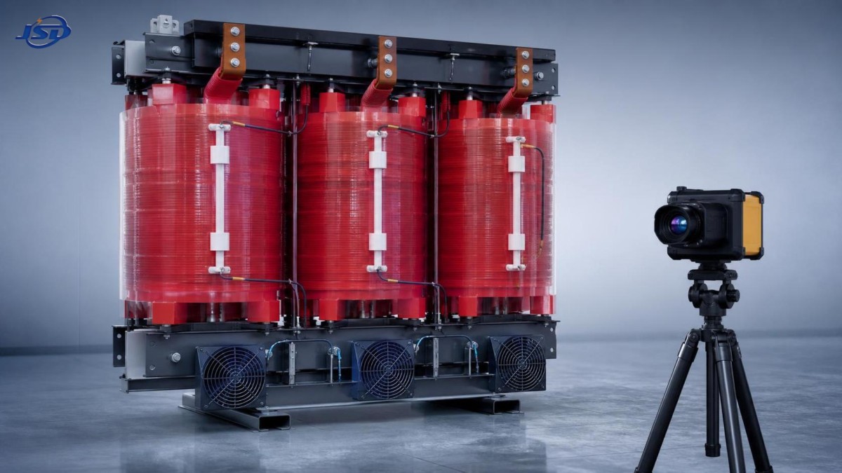
Cleaning Is a Thermal-Reliability Task
Cleaning is one of the most important maintenance activities for a cast resin dry type transformer, particularly in enclosed substations and industrial environments. The goal is not to make the unit look new. It is to restore the designed air paths and prevent deposits from reducing insulation surface resistance or retaining moisture.
Always de-energize, isolate, lock out, and verify absence of voltage before internal cleaning. Follow the manufacturer’s procedures and site safety rules. Loose dust is commonly removed with a properly rated industrial vacuum and dry, clean air at controlled pressure. Personnel should avoid forcing debris deeper into winding ducts, temperature sensors, terminal areas, or fan motors. Abrasive tools, aggressive solvents, and uncontrolled compressed-air cleaning can damage surfaces, dislodge wiring, or distribute contamination rather than remove it.
If deposits are oily, chemically aggressive, conductive, or difficult to remove, treat the condition as an investigation rather than a routine housekeeping issue. Identify the contamination source first: nearby machinery, cable-compound leakage, airborne process material, water intrusion, or inadequate enclosure sealing. Repeated cleaning without correcting the source turns a predictable operating problem into a recurring maintenance cost.
After cleaning, confirm that ventilation openings are unobstructed and that no cloth, debris, loose hardware, or tools remain in the enclosure. On units with forced-air cooling, inspect fan guards, fan blades, motors, wiring, contactors, and air direction. Forced-air capability should only be relied upon when the complete cooling system has been tested and is available.
Temperature Monitoring Must Be Interpreted, Not Merely Recorded
Most modern dry-type transformer installations use winding temperature indicators, resistance temperature detectors, thermistors, or a temperature protection and control system. These devices are essential, but an alarm value alone does not explain the cause of a high temperature.
When a temperature alarm occurs, review phase loading, ambient temperature, fan status, ventilation, harmonic content where relevant, and the recent loading history. Compare the readings among phases. A uniform increase across all phases may reflect high ambient temperature, overloaded operation, or blocked ventilation. A significant phase-to-phase difference can point to unbalanced load, a bad connection, an incorrect sensor position, localized cooling restriction, or a winding concern.
The response should be based on a trend. A winding temperature that has always operated near a known level is different from one rising gradually under the same load and ambient conditions. Maintenance records should capture the measured temperature, load current, room temperature, fan operating state, alarm status, and corrective action. This simple discipline allows maintenance teams to distinguish an isolated event from insulation-aging stress.
Do not assume that a stated overload capability permits unrestricted operation. For example, a unit designed for forced-air operation may be able to carry 120% rated load under specified conditions, but that capability depends on the applicable design, ambient conditions, ventilation performance, temperature limits, and duration. It is not a substitute for confirming that the transformer and its cooling controls are operating as intended.
Electrical Checks During Planned Outages
Periodic offline testing should be selected according to transformer rating, criticality, age, fault history, and the governing maintenance standard or owner specification. Test results are most useful when compared against commissioning values and previous test records. One isolated result without a baseline can be difficult to interpret.
Some owners also specify partial discharge testing, dielectric loss measurements, or other advanced diagnostic work after a fault, during acceptance testing, or where operating conditions justify it. These tests should not be added casually. They require suitable test methods, experienced interpretation, and a clear reason for the data. The correct approach is to follow the manufacturer documentation, project requirements, and applicable IEC, GB, or local standards rather than applying a single generic test package to every transformer.
Pay Attention to Protection, Fans, and Auxiliary Circuits
Many transformer failures are not caused by the cast-resin winding itself. They escalate because the warning, cooling, or tripping system was unavailable. During scheduled maintenance, test temperature-controller indications, alarm contacts, trip contacts, fan-start stages, manual and automatic fan modes, and remote signals to the building management system or SCADA system where installed.
Verify sensor wiring and identify which sensor corresponds to each phase. A controller may show a plausible value even when a sensor has been incorrectly connected or has drifted out of expected behavior. Test records should include actual observed switching points, not simply a checkbox stating that the controller was inspected.
Protection coordination also matters after system changes. A new large motor, variable-frequency drive, capacitor bank, inverter, or parallel transformer can alter fault levels, harmonic exposure, and load balance. When the electrical system changes materially, revisit transformer protection settings and loading assumptions. A maintenance department should not inherit a revised operating condition without receiving the relevant commissioning and protection information.
Common Assumptions That Create Avoidable Risk
The first misleading assumption is that epoxy encapsulation makes moisture irrelevant. The winding insulation may resist moisture well, but condensation, dust, corroded terminals, cable-box ingress, and tracking across contaminated external surfaces remain real risks. The second is that F1 fire performance or a non-flammable insulation system eliminates the need to control temperature. Fire performance and thermal aging are related to different operating questions.
A third assumption is that a clean room always means a clean transformer. Fine dust can accumulate in winding passages and on top surfaces long before it is obvious from the entrance of the electrical room. The fourth is that an alarm is a maintenance event rather than an operating event. Temperature alarms should trigger an immediate assessment of load, cooling, and protection behavior, followed by a documented technical review.
Finally, maintenance teams should avoid treating all dry-type transformer designs as interchangeable. Voltage class, insulation class, enclosure design, winding construction, cooling arrangement, tap configuration, accessories, and local environmental conditions affect the inspection plan. For reference, a 33kV Cast Resin Dry-Type Distribution Transformer used to step down to a low-voltage distribution system may require particular attention to high-voltage termination condition, lightning and surge exposure, temperature-control functionality, and the availability of forced-air cooling where overload operation is part of the operating strategy.
When an Abnormal Condition Needs Escalation
Maintenance personnel should escalate rather than simply reset and monitor when there is repeated temperature alarming, unexplained phase temperature deviation, visible tracking or carbonization, cracking associated with thermal evidence, persistent abnormal noise, a post-fault change in test values, evidence of terminal overheating, damaged resin around connections, or a protection device that fails functional testing.
After a short circuit or major external fault, do not assume normal appearance proves normal internal condition. Mechanical forces can affect windings and connections even when there is no obvious external damage. Review the fault magnitude and duration, inspect the unit, perform the tests justified by the event, and obtain manufacturer guidance when results or symptoms are uncertain.
The most effective maintenance program is therefore a disciplined loop: inspect, measure, compare, correct, and record. Cast-resin technology reduces several traditional transformer maintenance burdens, but reliability still depends on clean cooling paths, trustworthy temperature protection, sound electrical joints, and records good enough to show when normal operation is beginning to change.

Get a Quote
Regardless of whether you require general advice or specific support, we are happy to help you.
Send Us Your Inquiry Today

Jinshida Electric remains committed to contributing to global energy development through professional manufacturing and superior service.