





Three-Phase Transformer Factory Audits: Winding, Drying, and Test Controls
A transformer can pass final electrical tests while its manufacturing records still reveal uncontrolled insulation handling, undocumented winding repairs, or inadequate drying verification. During an electrical three phase transformer factory audit, these gaps matter because a satisfactory test result does not establish long-term insulation reliability—and a complete test report does not prove that the test area is safe.
The strongest audit follows one identifiable transformer from approved drawings and incoming materials through winding, insulation processing, drying, assembly, and final testing. Compare actual shop-floor practices with controlled procedures, then verify that acceptance limits, measurement records, and release decisions are traceable. Start with winding accuracy, moisture control, and test-area safeguards rather than treating certificates as sufficient evidence.
Set the acceptance basis before entering production
Request the purchase specification, approved drawings, inspection and test plan, applicable standards, and any agreed deviations. Establish whether the unit is liquid-immersed, cast-resin, or another dry-type design. The insulation system determines which manufacturing controls are relevant; a liquid-immersed transformer's cellulose drying records cannot simply be substituted for a cast-resin unit's curing controls.
For projects using IEC requirements, the IEC 60076 series provides the principal transformer framework, with applicable parts selected according to construction and test scope. IEC 60076-11 addresses dry-type transformers. Where IEEE requirements apply, IEEE C57.12.00 and C57.12.90 are relevant to liquid-immersed equipment, while dry-type equipment uses different applicable documents. Confirm the contractual editions and requirements instead of mixing acceptance criteria from separate systems.
A quality management certificate describes a management-system scope, not the conformity of every transformer. Verify its validity, covered manufacturing location, and activities, but assess product compliance through design documents, process evidence, and test results. Type-test evidence also needs a documented relationship to the supplied design; a report for a materially different insulation arrangement or rating may not establish applicability.
- Define release points: Identify inspections required before winding concealment, tank closure, resin casting, or shipment.
- Separate test categories: Establish which routine tests apply to every unit and which type or special tests require representative evidence or contractual agreement.
- Record responsibilities: Confirm who may approve deviations, accept rework, witness tests, and authorize shipment.
Follow material identity into the winding station
Select an available production unit and trace its serial number back to conductor, insulation, and core-material records. Material identity should survive cutting, splitting, and transfer between workstations. An incoming certificate is weak evidence if the conductor actually loaded onto the winding machine cannot be linked to it.
Compare conductor dimensions, insulation build, and material specifications with the approved bill of materials. For paper and pressboard, inspect storage conditions, packaging integrity, and exposure tracking where required by the process. Look for opened materials beside wet cleaning operations, uncontrolled outdoor transfers, or unidentified remnants returned to stock. These conditions create uncertainty even when incoming inspections were acceptable.
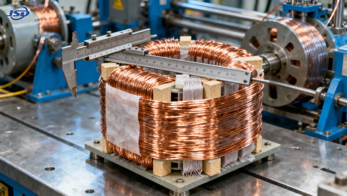
At the winding machine, check the current drawing revision and the setup record together. Turn count, winding direction, tap positions, conductor arrangement, insulation placement, and cooling ducts must match the design. Machine settings are supporting evidence, not proof: counters can be reset, operators can change tension, and repairs can alter geometry without updating the traveler.
Inspect controls that final ratio testing cannot replace
A turns-ratio test can help identify connection or turn-count problems, but it does not confirm every local insulation detail or mechanical support condition. Review how the factory controls conductor tension, bend radii, crossover insulation, spacers, end insulation, and axial dimensions. Uneven winding geometry can affect cooling passages and the mechanical behavior under fault forces.
Ask to see a completed in-process inspection record before the winding becomes inaccessible. It should identify the inspected features, acceptance basis, operator or inspector, and disposition of any defect. Entries such as “checked” without dimensions or defined criteria offer little evidence for critical characteristics.
Joint preparation deserves separate attention. Whether the process uses brazing, welding, or another approved method, verify procedure control, operator qualification where specified, insulation restoration, and inspection. Reworked joints or damaged conductor insulation should have an approved repair route rather than being accepted solely because continuity remains intact.
Drying records must demonstrate a controlled endpoint
For cellulose-insulated liquid-immersed transformers, residual moisture can impair dielectric performance and accelerate insulation aging. The audit question is not simply whether a drying oven or vacuum plant exists. It is whether the approved cycle is suitable for the insulation mass, assembly geometry, and processing method—and whether each load reached a defined endpoint.
Request actual cycle histories, not just the standard recipe. Review load identification, temperature measurement locations, heating duration, vacuum conditions where applicable, interruptions, and endpoint evidence. Depending on the process, endpoint assessment may involve moisture extraction trends, condensate measurement, pressure behavior, insulation samples, or other validated indicators. No single indicator should be treated as universally sufficient.
Distinguish chamber readings from conditions within the insulation assembly. A chamber reaching its setpoint does not necessarily mean the thickest insulation section has reached the required temperature. Check sensor placement and how the factory validated its process for different load sizes. Vacuum gauges and temperature instruments also need calibration suitable for their operating ranges.
After drying, inspect the transfer route to tanking and filling. Controlled holding conditions, exposure-time limits, dry-air or nitrogen protection where specified, and documented responses to delays help prevent moisture reabsorption. For liquid-immersed units, oil handling, filtration, vacuum filling, and relevant oil-quality checks must connect to the same release record.
For cast-resin windings, examine resin preparation, component storage, mixing ratios, degassing, casting conditions, and cure-cycle records instead. Confirm how the manufacturer detects and dispositions voids, cracks, or incomplete curing. These controls serve the same insulation-integrity objective but require a different evidence chain.
Match final tests to the actual transformer
Before reviewing results, reconcile the nameplate, approved connection diagram, serial number, tap configuration, and test-sheet identity. A technically plausible report is still unacceptable if it belongs to another unit or a different connection arrangement. Test software should preserve raw readings and identify corrections, retests, and report revisions.
Review the applicable routine-test package, typically including winding resistance, voltage ratio and phase displacement, losses, impedance, and specified dielectric tests. The exact package depends on transformer construction and the governing requirements. Insulation-resistance measurements may support assessment, but they do not replace required dielectric tests or constitute a universal moisture acceptance criterion.
For resistance and loss measurements, check recorded temperatures and the correction method required by the applicable standard. For three-phase measurements, confirm that connections and phase identification follow the approved test procedure. Investigate unexplained phase differences rather than accepting a single “pass” field generated by software.
Dielectric testing requires the correct test configuration, voltage, duration, sequence, and interpretation for the design. Applied-voltage, induced-voltage, impulse, and partial-discharge requirements are not interchangeable. Some depend on insulation level, equipment category, or agreed test scope; the factory should explain why each test is included or excluded.
Check measurement-system suitability as well as calibration status. Relevant issues include instrument range, resolution, uncertainty, current-transformer and voltage-transformer performance, and power measurement at low power factor. When a result is close to an acceptance limit, request the agreed decision rule and technical review rather than rounding it into compliance.
Audit the test bay as a hazardous-energy workplace
A well-documented transformer can still be tested in an unsafe facility. Observe the test bay from an authorized position and verify that personnel cannot enter an energized zone inadvertently. Barriers, access control, warning indicators, interlocks where required, emergency isolation, and defined energization authority should function as a coordinated system.
Look for a controlled sequence covering isolation, connection, pre-energization checks, testing, de-energization, discharge, verification, and grounding before access. A switched-off supply is not evidence that stored energy has dissipated. The procedure must address the actual sources of hazardous energy, including connected test equipment and induced or capacitive effects.
- Confirm that connection changes occur only under the approved safe-isolation procedure.
- Check inspection records for grounding leads, discharge devices, cables, and protective barriers.
- Review how interlock bypasses are authorized, recorded, and prevented from becoming routine.
- Verify emergency arrangements and training appropriate to the site's electrical hazards and local requirements.
Extend the safety review to production where relevant: coil handling, lifting fixtures, oven access, vacuum vessels, hot work, resin chemicals, and oil operations. Witnessing a test does not justify entering an exclusion zone. Unsafe conditions should be corrected before the demonstration continues.
Renewable-energy interfaces add design questions, not exemptions
When a transformer connects a battery storage system or power converter, manufacturing conformity must be assessed against the intended duty. The 500kW/1MWh Air Cooling Container Energy Storage System, for example, specifies a 500 kW PCS and a 400 V AC three-phase four-wire output, with 50 Hz or 60 Hz operation. Those interface details help frame a transformer specification; they do not establish that a particular transformer is included or suitable.
Before accepting the associated transformer design, confirm apparent-power requirements, converter harmonics, grounding and neutral arrangements, voltage ratio, frequency, protection coordination, and site conditions. Do not select transformer kVA from the 500 kW figure alone. Obtain the converter's operating envelope and use it to establish the thermal and electrical duty that manufacturing and testing must support.
Close findings with evidence tied to shipment release
Classify findings by their effect on safety, conformity, and traceability. Missing proof that a unit completed its drying cycle is different from an administrative typo with an intact evidence trail. An uncontrolled dielectric-test area requires immediate operational action; an obsolete work instruction requires assessment of which units were produced under it.
Each significant finding should identify the affected equipment, unmet requirement, containment action, corrective action, and verification needed for closure. Where rework occurs, define the inspections or tests required afterward and retain the original failure record. Repeating a test until it passes is not an adequate disposition unless the failure mechanism has been investigated and the corrective action justified.
Shipment release should depend on resolved acceptance-critical findings and an authorized review of the completed manufacturing record. Where drying evidence, concealed winding quality, or design-test applicability remains uncertain, require a documented engineering disposition before acceptance—not an unsupported assurance that final testing covers the gap.

Get a Quote
Regardless of whether you require general advice or specific support, we are happy to help you.
Send Us Your Inquiry Today

Jinshida Electric remains committed to contributing to global energy development through professional manufacturing and superior service.