





Replacing a 1500 kVA ONAN Transformer: Compatibility Checks Before Ordering
A replacement 1500 kVA ONAN transformer can have the same capacity and voltage ratings as the existing unit and still require changes to cables, protection settings, foundations, or operating procedures. Treat it as a direct replacement only after checking its electrical characteristics, connection interfaces, and installation requirements against the actual site.
The most useful starting point is a comparison between the existing transformer, the network requirements, and the proposed replacement. The old nameplate provides part of that comparison, but drawings, protection records, loading data, and a site survey establish whether the new unit can be installed and energized within the planned outage. Resolve differences that affect system performance before issuing the purchase order.
Establish the electrical match beyond the nameplate rating
First confirm what the replacement must supply. A 1500 kVA rating expresses apparent power capacity under specified operating conditions; it does not establish compatibility with a particular network. Record the primary and secondary rated voltages, frequency, winding connections, vector group, neutral arrangement, tap range, and the existing operating tap position. Compare these with the proposed transformer’s guaranteed schedule.
For an 11 kV/0.4 kV three-phase unit, rated current is approximately 79 A on the primary side and 2165 A on the secondary side, calculated from current = apparent power ÷ (√3 × line voltage). These values help assess connection requirements, but cable and busbar suitability also depends on installation conditions, temperature, fault duty, and the applicable design rules.
Voltage ratio, taps, and frequency
Check the voltage available at the transformer terminals and the voltage required at the load. Copying the existing nominal ratio can preserve a voltage problem if the supply conditions or downstream demand have changed. Review representative operating voltages, especially where long feeders, large motor starts, or substantial load variation affect the secondary voltage.
Specify each required tap position and the corresponding voltage ratio. An identical percentage range does not necessarily mean identical steps or switching arrangements. Establish whether the tap changer operates off circuit or under load, and whether the selected setting produces an acceptable secondary voltage across expected conditions. An off-circuit tap changer requires the transformer to be de-energized before adjustment.
Frequency must also match the application. A transformer intended for a different frequency cannot be accepted solely because its voltage and capacity appear suitable. Obtain the manufacturer’s assessment for the proposed voltage-to-frequency conditions if the replacement specification differs from the original installation.
Vector group, neutral, and insulation levels
The vector group defines winding connections and phase displacement. A change can affect phase relationships across a bus coupler, transfer arrangement, or parallel connection. Check phase identification and terminal markings as well: matching vector-group codes do not prove that the site cables will land in the correct sequence.
Confirm whether the low-voltage neutral must be brought out, how it connects to the earthing system, and what continuous and fault duties it must support. Any change to winding connections or neutral availability requires a review of earth-fault protection and the network earthing arrangement.
Specify the highest voltage for equipment and the required dielectric withstand levels for each winding. Rated operating voltage alone does not define insulation coordination. The selected levels must suit the network, surge protection, cable connections, and project requirements. A catalogue impulse rating is useful only when it applies to the offered winding and configuration.
Check impedance against fault duty, protection, and parallel operation
Short-circuit impedance deserves an explicit acceptance criterion. It influences prospective fault current, voltage regulation, and load sharing between transformers. A replacement with lower impedance may increase fault duty beyond the capability of existing low-voltage equipment. A higher-impedance unit may produce greater voltage drop during heavy loading or motor starting.
As a simplified illustration, a 1500 kVA, 400 V transformer with 6% impedance has a transformer-limited terminal fault current of approximately 36 kA when upstream source impedance is ignored. At 5% impedance, the same calculation gives approximately 43 kA. These are illustrative values rather than a complete fault study: source impedance, cables, operating configuration, and other fault contributions affect the result.
The comparison nevertheless shows why “close enough” impedance can have consequences. Recalculate fault levels using the proposed transformer’s guaranteed impedance and applicable tolerance. Check switchboard withstand ratings, breaker interrupting capacity, and cable fault duty. Use the relevant impedance components or X/R information where the study requires them, particularly for peak current and protection performance.
Protection settings also need review. Existing settings may have been selected for the original transformer’s thermal limits, inrush characteristics, impedance, and fault levels. Check overcurrent and earth-fault coordination, differential protection where fitted, CT ratios and polarity, and the treatment of magnetizing inrush. Retaining the same capacity does not establish that every relay setting remains appropriate.
Parallel operation raises the acceptance threshold
If the replacement will operate in parallel with another transformer, assess the pair together. Relevant conditions include compatible phase displacement and polarity, closely matched voltage ratios at the selected taps, compatible percentage impedances, and suitable impedance characteristics. Unequal ratios can cause circulating current; unequal impedances can cause one unit to reach its loading limit while spare capacity remains in the other.
The operating scheme matters as much as normal service. A normally open bus coupler may close during maintenance or supply transfer, creating a parallel condition that the replacement must accommodate. Record every permitted configuration and distinguish continuous parallel operation from brief overlap during switching.
Obtain a documented compatibility assessment using information for both transformers. Where the existing unit’s records are incomplete, establish whether measurements or further engineering assessment are necessary before accepting the replacement. The supplier’s confirmation should address the actual pairing and operating arrangements.
Prove that the replacement fits and can deliver 1500 kVA at the site
ONAN identifies oil natural circulation and air natural cooling. The specified 1500 kVA must be available under the agreed ambient temperature, altitude, and installation conditions. A transformer carrying that rating under different service conditions may need derating or a revised design at the replacement site.
Review the load profile rather than relying on a single maximum-demand reading. Sustained loading, recurring overloads, harmonic currents, and restricted heat dissipation can change the thermal assessment. If additional capacity depends on fans, document the separate cooling rating and auxiliary requirements. Fan-assisted output should not be treated as the transformer’s ONAN capacity.
For indoor installations, assess room ventilation and the heat released by transformer losses. Outdoors, check radiator clearances and exposure conditions. Specify the insulating liquid and cooling arrangement, including whether the unit is sealed or conservator-equipped. A change in liquid or tank arrangement may affect fire provisions, containment, maintenance access, and protection accessories.
Physical compatibility requires a dimensional drawing tied to the offered configuration. Overall length, width, and height are only the beginning. Terminal position and orientation can determine whether existing cables or busduct can be reused without major work.
- Connections: Check HV and LV terminal coordinates, phase order, neutral position, bushing or connector interfaces, cable-box dimensions, and cable entry direction.
- Supporting structure: Compare total operating mass, base dimensions, wheel or skid arrangement, fixing points, and loads on the foundation.
- Access: Check the transport route, door openings, lifting points, available crane access, and any components removed for delivery.
- Service space: Allow access to tap controls, instruments, valves, sampling points, radiators, and protection devices.
- Site provisions: Check electrical clearances, earthing points, oil containment, and interfaces with the existing fire and drainage arrangements.
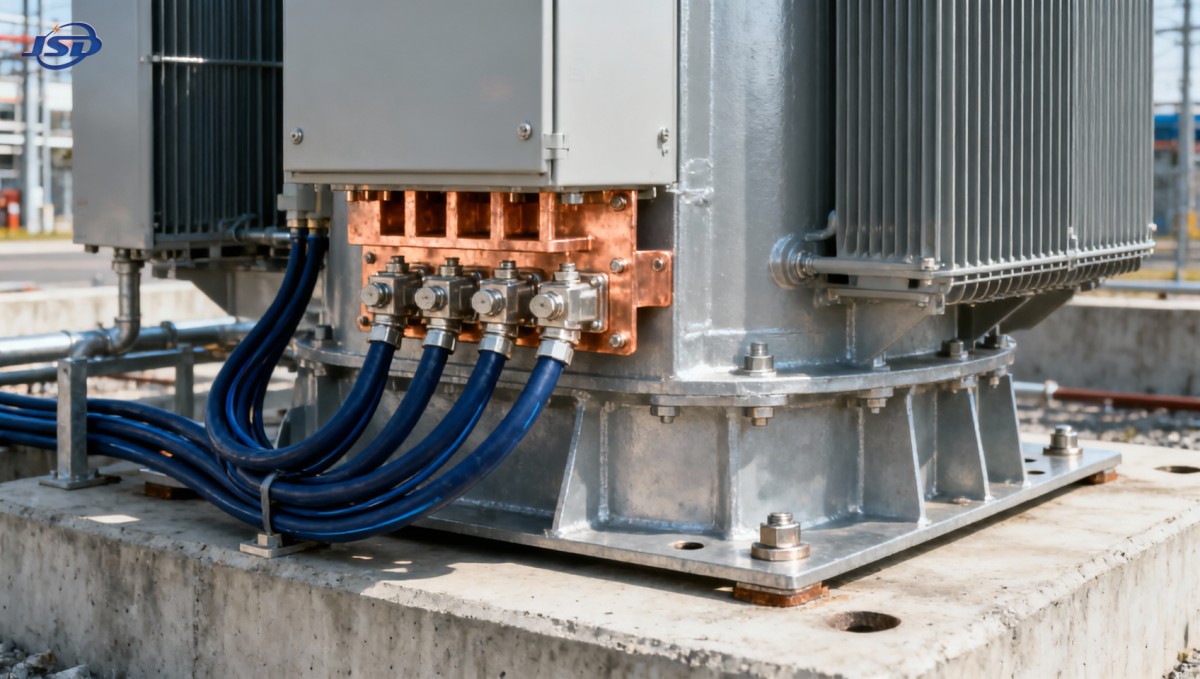
A cable termination can be electrically compatible yet physically unusable if the new cable box leaves insufficient bending space. Similarly, a transformer that fits inside the room may still be impossible to move through the entrance or maintain after installation. Compare the supplier’s drawing with measured site dimensions, including connection heights and obstructions.
A dry-type alternative changes the replacement scope
An indoor project may justify evaluating cast-resin construction where liquid containment or fire provisions constrain the installation. Jinshida Electric’s 11kV Three-Phase Cast Resin Dry-Type Distribution Transformer includes a 1500 kVA option for 11 kV/0.4 kV applications, with a listed short-circuit impedance of 6%. Those characteristics provide a starting point for evaluating an alternative.
Cast-resin construction uses different cooling designations and has different thermal, enclosure, and protection interfaces. Substituting it for an ONAN unit requires a review of ventilation, clearances, environmental conditions, terminations, and temperature monitoring. Any forced-air overload capability must be assessed separately from its natural-air rating. Such a substitution should proceed as an installation redesign, with its own acceptance criteria.
Make the order depend on documented compatibility
A procurement specification should separate fixed interface requirements from characteristics that may change following engineering review. Voltage ratio, vector group, required neutral arrangement, connection interfaces, and dimensional limits may be essential constraints. Losses, impedance, accessories, and cooling details also need stated requirements, with any proposed deviation assessed for its effect on the installation.
Define the applicable transformer standard and edition, together with utility or project requirements. Liquid-filled and dry-type designs have different relevant requirements within standards such as the IEC 60076 series. A broad claim of compliance does not establish that the offered transformer meets every requirement of the replacement project.
Agree the documentation and test scope before ordering. The supplier’s package should include a guaranteed technical schedule, general arrangement and terminal drawings, accessory details, control wiring diagrams, and the agreed test plan. Specify which routine test results must accompany delivery and what type or special test evidence is needed for the selected design. Management-system certification supports supplier assessment but does not replace equipment-specific evidence.
Protection accessories deserve their own interface check. Depending on the design, these may include oil and winding temperature devices, pressure relief or pressure monitoring, and gas-operated protection where applicable. Confirm alarm and trip functions, contact ratings, auxiliary supply requirements, and remote signal connections. A protection device has limited value if the existing control system cannot receive or act on its output.
Use an explicit deviation schedule during technical evaluation. Each difference should state its consequence, the work required, and who is responsible. A shifted LV terminal arrangement might require a busduct modification; a different temperature device might require control wiring changes; altered impedance might require a protection study. These items affect both installed cost and outage duration.
Before releasing the order, the evaluator should be able to answer three practical questions: will the transformer operate correctly in every permitted network configuration, can it be installed within the available space and outage, and do the drawings and guaranteed data support those conclusions? Any unresolved difference that could alter connections, fault duty, or thermal capacity belongs in the technical review before manufacture begins.

Get a Quote
Regardless of whether you require general advice or specific support, we are happy to help you.
Send Us Your Inquiry Today

Jinshida Electric remains committed to contributing to global energy development through professional manufacturing and superior service.