





Why a zig zag grounding transformer creates a neutral point
Why a Zig Zag Grounding Transformer Creates a Neutral Point
A zig zag grounding transformer creates a neutral point by combining phase windings in a balanced configuration that provides a stable path for zero-sequence and ground-fault currents.
For engineers researching ungrounded or delta-connected systems, understanding this principle is essential for improving fault protection, system reliability, and operational safety.
The central idea is straightforward: a zig zag transformer does not need a conventional neutral conductor on the source winding to establish a usable system neutral.
Instead, its specially interconnected windings make the normal three-phase voltages cancel while allowing zero-sequence current to flow during an earth fault.
This distinction explains why zig zag grounding transformers are widely used where a delta system, converter transformer, generator bus, or isolated network lacks an accessible neutral.
They are not primarily installed to transfer load power. Their principal role is grounding, fault-current control, and providing a reference point for protective devices.
What Problem Does a Neutral Point Solve?
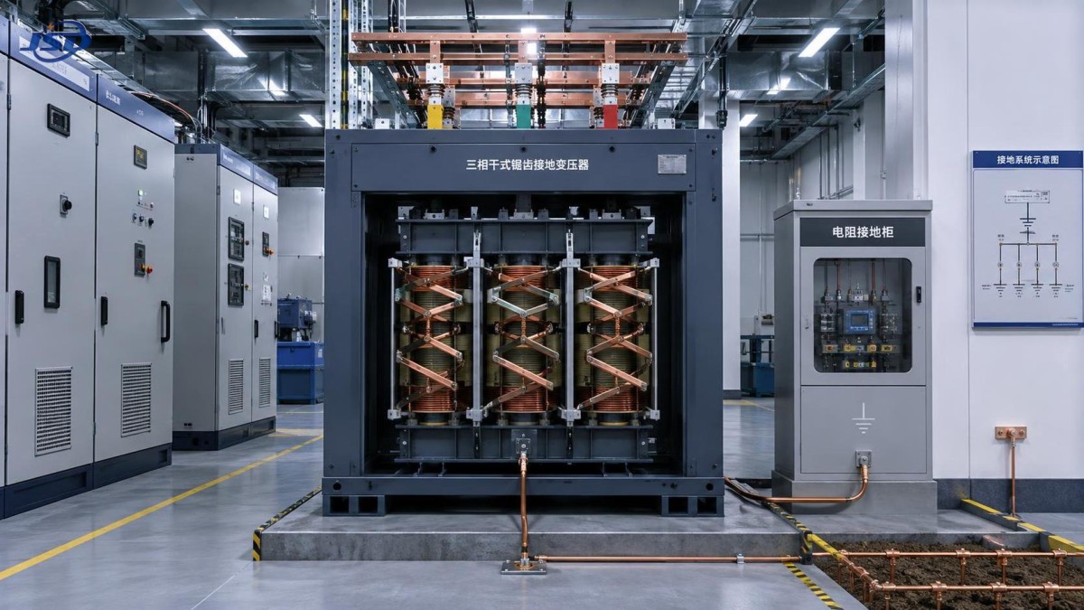
Many medium-voltage systems are operated with delta-connected windings or otherwise have no physical neutral point available at the bus being protected.
Without a neutral reference, a single line-to-ground fault may produce low, unpredictable, or mainly capacitive fault current, depending on system capacitance.
That condition can make conventional overcurrent protection less dependable. It can also allow temporary overvoltages on the two unfaulted phases after an earth fault.
In an ungrounded system, the first fault may not immediately interrupt service. However, insulation stress and the risk of a second fault can increase.
A grounding transformer creates a defined connection between the electrical system and earth, allowing engineers to select a deliberate grounding method.
The grounding method may be solid grounding, resistance grounding, or reactance grounding, depending on protection goals and allowable fault-current limits.
For many industrial facilities, resistance grounding is selected because it produces enough current for reliable detection without causing excessive equipment damage.
The transformer therefore gives protection relays a reference and gives fault current a designed return path rather than leaving system behavior uncontrolled.
How the Zig Zag Winding Arrangement Works
A zig zag grounding transformer has three phase limbs, but each phase winding is divided into two equal sections placed on different core limbs.
Each section is connected to a section associated with another phase. The resulting interconnection creates the characteristic zig zag winding pattern.
Under balanced three-phase operating conditions, the voltage contributions from the winding sections oppose each other and largely cancel at the neutral connection.
Because the phase voltages are balanced, the transformer has very low magnetizing demand and normally carries only a small current in service.
During a ground fault, the situation changes. The three phase currents associated with the fault are zero-sequence currents, sharing the same phase relationship.
For zero-sequence current, the winding section voltages no longer cancel in the same way. Instead, the transformer presents a low-impedance return path.
This enables current to flow from the faulted phase, through the grounding system, into the zig zag transformer neutral, and back through its windings.
The arrangement establishes a neutral point even though the upstream system may be delta-connected and has no neutral conductor available for direct grounding.
Why Normal Load Current Does Not Flow Through It
A common misunderstanding is that a zig zag grounding transformer behaves like an ordinary distribution transformer supplying a neutral load circuit.
Its normal operating behavior is different. Balanced positive-sequence load currents do not create a significant current path through the grounding transformer neutral.
The winding connections are designed so that balanced phase flux components offset each other, minimizing core excitation from the normal power system.
This is why a properly selected zig zag unit can remain lightly loaded during normal operation while still responding strongly during ground faults.
Its rating is therefore usually specified in terms of short-time ground-fault duty, impedance, voltage, and thermal capability rather than continuous load capacity alone.
For example, a grounding transformer may be designed to carry a specified fault current for ten seconds, thirty seconds, or another protection-clearing duration.
Engineers must coordinate that duty with relay operating time, breaker clearing time, grounding resistor capacity, and expected system fault characteristics.
Selecting only by nominal system voltage is insufficient. The fault-current duty and protection philosophy determine whether the transformer is appropriately sized.
What Happens During a Single Line-to-Ground Fault?
Consider a three-phase delta bus with no grounded neutral. A phase-to-ground fault occurs on one conductor downstream of the bus.
Without grounding equipment, fault current may be limited mainly by distributed cable capacitance, surge arresters, and other unintended system paths.
With a zig zag grounding transformer installed, the neutral point is connected to earth directly or through a grounding resistor.
The faulted phase then has an intentional return path. Current flows through the fault, the equipment grounding network, and the transformer neutral connection.
The zig zag windings return the zero-sequence component to the three-phase system while keeping normal phase-to-phase voltage operation largely unaffected.
Protective relays measure the resulting residual or ground current and command the appropriate circuit breaker or alarm system to operate.
The resistor, if included, limits the current to a planned value. This can reduce arc-flash energy, mechanical stress, and localized damage.
At the same time, fault current must remain above the protection pickup threshold under credible minimum-fault conditions, including long feeder runs.
Choosing Between Solid, Resistance, and Reactance Grounding
A zig zag grounding transformer can support several grounding strategies, but the transformer itself does not decide the final fault-current level.
Solid grounding connects the neutral directly to earth. It can produce high ground-fault current and is generally applied where rapid clearing is required.
Low-resistance grounding uses a neutral grounding resistor to permit a controlled, relatively high fault current for prompt selective protection operation.
High-resistance grounding limits current to a much lower level, often allowing continued operation after the first ground fault while an alarm is investigated.
Reactance grounding uses an inductor in the neutral circuit. It may be chosen where impedance characteristics or system coordination support that approach.
The correct option depends on voltage class, feeder length, cable charging current, equipment duty, process continuity requirements, and local electrical standards.
High-resistance grounding is not automatically safer for every system. If detection cannot identify the fault location, continued operation can create operational risk.
Likewise, excessive fault current may improve relay sensitivity but impose unacceptable thermal and mechanical stress on cables, switchgear, and transformers.
How to Size a Zig Zag Grounding Transformer
Sizing begins with the system line-to-line voltage, because the grounding transformer winding insulation must withstand the network’s operating and transient voltage conditions.
The next key value is required ground-fault current. This is often determined by relay sensitivity, resistor selection, and coordination with downstream protection devices.
Short-time thermal rating is equally important. The unit must survive the selected fault current for the full protection-clearing interval without damage.
Impedance affects available ground-fault current and relay performance. It should be evaluated together with the neutral resistor, source impedance, and feeder characteristics.
Engineers should also calculate total system charging current, particularly on extensive cable networks, renewable plants, data centers, and industrial distribution systems.
For high-resistance grounding, the selected neutral current commonly needs to exceed the system’s capacitive charging current by a suitable engineering margin.
Core design, insulation class, ambient temperature, installation environment, seismic requirements, and enclosure protection also affect the final equipment specification.
A manufacturer should receive the single-line diagram, voltage level, fault-clearing time, desired neutral current, grounding method, and protection scheme before quotation.
Where Zig Zag Grounding Transformers Are Commonly Used
Zig zag grounding transformers are frequently installed on medium-voltage delta buses serving industrial plants, mining operations, process facilities, and infrastructure projects.
They are also useful at renewable energy collector systems, where converter-based sources and step-up transformer connections may not provide an accessible neutral.
Data centers and hospitals may require carefully engineered grounding arrangements because continuity, selective fault isolation, and equipment protection are operational priorities.
In commercial or industrial distribution networks, they can be added during upgrades when the existing transformer connection does not offer a suitable neutral point.
The application must be reviewed as a complete grounding system. A grounding transformer cannot compensate for poor bonding, unsuitable relay settings, or inadequate earth electrodes.
Site conditions matter as well. Indoor dry-type equipment, outdoor oil-filled units, resistance enclosures, cable routing, ventilation, and maintenance access require coordinated planning.
How This Relates to Distribution Transformer Selection
A grounding transformer and a distribution transformer serve different electrical functions, although both must be selected within the broader power-system design.
The grounding transformer establishes and controls the neutral reference. The distribution transformer changes voltage and supplies the facility’s normal load demand.
For projects requiring reliable medium-voltage distribution, transformer selection should account for grounding philosophy before protection settings and switchgear ratings are finalized.
Jinshida supports distribution applications with equipment designed for dependable operation in industrial, commercial, infrastructure, and renewable-energy environments.
For example, the 35kV Three-Phase Cast Resin Dry-Type Distribution Transformer is available for 35 kV to 0.4 kV distribution applications.
Its cast-resin construction, high-quality grain-oriented silicon steel core, and epoxy insulation system suit installations where fire performance and low maintenance matter.
Available capacities cover a broad range of distribution requirements, while temperature protection and control systems support monitored operation in demanding facilities.
That product is not a substitute for a purpose-designed zig zag grounding transformer, but both may form part of a coordinated power distribution solution.
Common Design Mistakes to Avoid
One frequent mistake is assuming that any transformer neutral can be grounded without checking winding connection, insulation duty, and available zero-sequence current paths.
Another is specifying a zig zag grounding transformer without defining the resistor value, fault duration, relay pickup settings, and breaker clearing sequence.
Engineers sometimes focus only on maximum fault current. Minimum ground-fault current is also critical because protection must operate under unfavorable conditions.
Ignoring cable charging current can be particularly problematic in large medium-voltage networks, where capacitive current may affect high-resistance grounding performance.
Inadequate coordination between the grounding transformer and surge protection can leave equipment exposed to temporary overvoltages during abnormal operating conditions.
Grounding conductors, bonding connections, earth grid resistance, and neutral resistor enclosure ratings should be reviewed as part of the same design package.
Finally, do not treat a short-time rated grounding transformer as a continuous auxiliary transformer unless its manufacturer confirms that operating duty is permitted.
Questions to Ask Before Specifying Equipment
Start by identifying whether the source or bus has an accessible neutral. If it does, a separate grounding transformer may not be necessary.
Then define whether the objective is immediate fault clearing, controlled fault-current limitation, first-fault alarm operation, or a combination of these goals.
Ask what ground-fault current protective relays require, how quickly breakers clear, and whether downstream devices can withstand the resulting energy.
Confirm the system’s total cable capacitance, expected expansion, generator or inverter contributions, and possible operating configurations during maintenance or contingencies.
Request manufacturer documentation covering voltage rating, insulation level, impedance, short-time current rating, temperature rise, test standards, and connection diagrams.
For international projects, verify applicable IEC, IEEE, utility, and local code requirements early, rather than adapting the grounding arrangement after procurement.
Conclusion
A zig zag grounding transformer creates a neutral point because its divided, cross-connected windings cancel balanced three-phase effects while conducting zero-sequence fault current.
That electrical behavior makes it a practical grounding solution for delta and otherwise ungrounded systems where reliable earth-fault detection is required.
Its value lies in making ground-fault behavior intentional: current can be limited, measured, coordinated, and cleared according to a defined protection strategy.
For a sound specification, evaluate the full system rather than the transformer alone, including fault duty, resistor selection, relay settings, cables, and grounding infrastructure.
When those elements are coordinated, a zig zag grounding transformer can improve protection dependability, control equipment stress, and support safer long-term system operation.

Get a Quote
Regardless of whether you require general advice or specific support, we are happy to help you.
Send Us Your Inquiry Today

Jinshida Electric remains committed to contributing to global energy development through professional manufacturing and superior service.