





How a substation grounding transformer limits earth-fault overvoltage
An earth fault becomes dangerous in an isolated or high-impedance-grounded substation not simply because one phase touches earth, but because the healthy phases can rise substantially above their normal phase-to-earth voltage. A substation grounding transformer gives a network without an accessible neutral a controlled reference to earth. When it is correctly coordinated with a neutral grounding resistor or reactor, it limits the neutral displacement that drives earth-fault overvoltage while creating a defined current path that protection relays can detect.
The important distinction is that a grounding transformer does not eliminate every transient. Lightning impulses, switching surges, cable energization effects, and resonant conditions still require insulation coordination and surge-protection measures. Its primary contribution is to control the system response to single-line-to-ground faults and prevent the network from behaving like an uncontrolled floating system.
Why an ungrounded network can experience high earth-fault voltage
Many medium-voltage transformer windings are connected in delta, and some systems use ungrounded or impedance-grounded arrangements. These configurations may not provide a neutral point that can be connected directly to earth. Under normal balanced conditions, this is not necessarily a problem: each phase-to-earth voltage is established mainly by the distributed capacitance of cables, busbars, rotating machines, transformers, and connected equipment.
During a single-line-to-ground fault, the faulted phase is pulled close to earth potential. If there is no intentional grounding path, the neutral point shifts. The two unfaulted phases can then approach line-to-line voltage with respect to earth, rather than remaining near their normal phase-to-earth voltage. This increased duty affects cable insulation, transformer winding insulation, voltage transformers, surge arresters, switchgear, and connected motors.
Capacitive charging current also flows from the healthy phases through the network capacitance toward the fault. In a modest, compact system this current may be small. In cable-rich substations, renewable collector networks, industrial plants, or networks with many connected feeders, it can be large enough to sustain an arcing earth fault. An intermittent arc may repeatedly extinguish and restrike, producing steep transient overvoltages that are more severe than a steady-state neutral shift.
The controlled fault path changes the system response
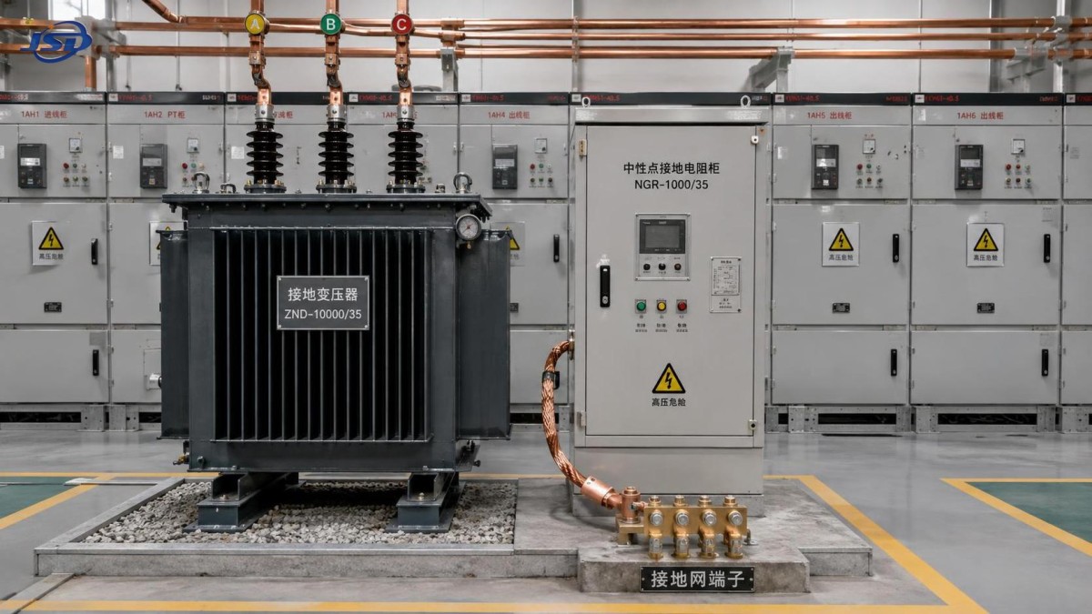
A grounding transformer is usually connected to the bus or transformer tertiary winding and is commonly configured in zig-zag or wye-delta form. Its winding arrangement produces a neutral point without acting as the main transformer that transfers bulk load power between voltage levels.
For positive- and negative-sequence currents, the magnetic effects in a zig-zag grounding transformer largely cancel. For zero-sequence current, however, the winding sections reinforce one another and provide a low-impedance magnetic path to the neutral. Connecting the neutral to earth directly, through a resistor, or through a reactor establishes the intended zero-sequence grounding circuit.
During an earth fault, current follows a controlled route:
- from the energized phase to the fault location and earth;
- through the substation earthing system to the grounding-transformer neutral connection;
- through the grounding transformer and its connected neutral grounding impedance;
- back to the source through the zero-sequence network.
This path limits how far the system neutral can move and determines the earth-fault current available to protective relays. The design objective is not always to maximize fault current. A solidly grounded arrangement may produce enough current for rapid, selective tripping, but it can increase damage at the fault point. Resistance grounding intentionally restricts current, reducing thermal and arc-flash stress while still providing a measurable residual or neutral current. Reactor grounding may be selected where the aim is to compensate for capacitive earth-fault current, although its response must be assessed carefully as the connected network changes.
How this limits earth-fault overvoltage in practice
The overvoltage-limiting mechanism has three connected parts. First, intentional grounding gives the neutral a defined voltage reference. This prevents the healthy phases from freely rising toward full line-to-line voltage to earth during a sustained fault.
Second, the selected grounding impedance controls the magnitude and phase relationship of zero-sequence current. A resistor introduces damping. That damping is especially valuable where intermittent faults and system capacitance could otherwise create repeated transient recovery voltages. A reactor changes the reactive balance of the grounding circuit and can reduce fault current in an appropriately designed compensated network, but poorly matched reactance can leave a system prone to resonance or difficult-to-detect faults.
Third, the grounding transformer makes protection dependable. A fault that produces only capacitive current may be difficult to locate selectively. Once a defined grounding branch exists, relays can use neutral current, residual current, residual voltage, directional elements, or a combination of these quantities. Faster and more selective fault clearance reduces the time that insulation is exposed to abnormal phase-to-earth voltage.
That last point is often missed in design reviews: voltage control and protection sensitivity are not separate decisions. A grounding impedance that reduces fault current very aggressively may reduce damage, but it can also leave too little reliable signal for the installed relay scheme. Conversely, a low impedance may simplify protection but impose greater fault duty on equipment and the earthing grid. The grounding transformer, neutral grounding device, relay settings, feeder configuration, and insulation coordination should therefore be evaluated as one system.
The transformer rating must follow the grounding duty
A grounding transformer is not selected by the load MVA of the bus. Its critical rating is its ability to carry earth-fault current for the required duration without unacceptable thermal or mechanical stress. The evaluator needs the expected ground-fault current, clearing time, allowable overload duty, voltage level, insulation class, and the number of potential fault events considered in the design philosophy.
Continuous losses and auxiliary burdens may also matter, but they do not replace the short-time zero-sequence duty calculation. A unit can appear adequately sized from a conventional transformer perspective while being unsuitable for a prolonged ground-fault duty.
At the main transformation level, the grounding arrangement also affects insulation and protection assumptions for the power transformer. For regional substations and new-energy step-up facilities, an 110kV Oil-Immersed Transformer may form part of the wider voltage-transformation scheme, while a separately designed grounding transformer establishes the neutral behavior of the relevant bus. They serve different functions: the power transformer transfers energy; the grounding transformer manages zero-sequence fault behavior. Treating the neutral point of a power transformer as automatically suitable for every grounding requirement is a common design error.
Questions that expose weak grounding-transformer specifications
A procurement specification that only states the system voltage and asks for a “grounding transformer” is incomplete. The following checks reveal whether the design basis is mature:
- Is the bus delta-connected or otherwise without a usable neutral? If an existing transformer neutral is available, its grounding capability, insulation arrangement, and fault-duty rating must still be assessed before using it.
- What is the total phase-to-earth capacitance of the connected network? Cable additions, long feeders, filter banks, rotating machines, and new inverter-based generation can change earth-fault behavior materially.
- What fault current is intended and why? The answer should connect equipment damage limits, relay pickup requirements, selectivity, and operating philosophy.
- What is the maximum clearing time? This governs the short-time rating of the grounding transformer and neutral resistor or reactor.
- Which faults must be detected? A feeder fault, a bus fault, and a high-resistance fault may require different relay elements and sensitivity margins.
- How will the scheme behave after network expansion? Grounding designed around today’s cable charging current can become unsuitable after additional feeders or new energy collector circuits are connected.
Resistance grounding, reactance grounding, and solid grounding are not interchangeable
No option is automatically better. The correct choice depends on whether immediate fault isolation is required, whether temporary operation with an earth fault is permitted by the operating philosophy, how much cable capacitance exists, and whether equipment is designed for the resulting phase-to-earth stresses.
Do not confuse an earth grid with system grounding
A substation earth grid is essential for personnel safety and for bonding exposed conductive parts. It controls touch and step voltages by providing a low-impedance connection to the physical earth. It does not, by itself, guarantee controlled zero-sequence behavior in the electrical network.
System grounding requires an intentional connection between the power system neutral, or an artificial neutral created by a grounding transformer, and the earthing system. A well-designed grid with no suitable neutral reference can still leave a delta or isolated bus exposed to neutral displacement and difficult earth-fault detection. The two functions must be designed together, but they answer different problems.
Commissioning evidence matters as much as the nameplate
Before energization, the grounding path should be checked from the bus connection through the transformer windings, neutral grounding device, relay inputs, and substation earth grid. Polarity and wiring errors in residual-current circuits can defeat directional protection even when the equipment itself is correct. The neutral grounding resistor or reactor must be verified for its specified duty, and relay settings should be tested against credible minimum and maximum earth-fault conditions.
For an existing substation, reassessment is warranted after substantial cable additions, a bus reconfiguration, installation of capacitor banks, or grid connection of photovoltaic, wind, or energy-storage facilities. These changes can alter zero-sequence impedance and capacitive charging current enough to change both overvoltage exposure and protection performance.
The most defensible evaluation starts with the actual zero-sequence network, not with a catalog rating. Establish the available neutral point, calculate or model the earth-fault current and voltage displacement, select grounding impedance around protection and equipment limits, then confirm that the grounding transformer can carry the specified duty. When those decisions agree, the grounding system does more than satisfy a drawing requirement: it keeps a single earth fault from becoming an insulation and protection-coordination problem across the substation.

Get a Quote
Regardless of whether you require general advice or specific support, we are happy to help you.
Send Us Your Inquiry Today

Jinshida Electric remains committed to contributing to global energy development through professional manufacturing and superior service.