





How to size a neutral grounding transformer for fault current
A neutral grounding transformer should not be sized from transformer capacity alone, nor from the prospective three-phase short-circuit level. Its primary purpose is to create a neutral reference and establish a controlled return path for single line-to-ground faults on an otherwise ungrounded or delta-connected medium-voltage system. The correct rating is therefore driven by the required ground-fault current, the actual zero-sequence network, the protection clearing time, and the thermal duty imposed on both the transformer and the grounding resistor.
The key decision is not simply “how large should the transformer be?” It is: what fault current must flow, for how long, through what grounding impedance, and with what protection sensitivity? A grounding transformer that is electrically too weak may overheat during a fault. One selected with excessive impedance may prevent relay pickup. One designed for unnecessarily high current can increase arc-flash energy and damage at the fault point without improving protection performance.
Start with the intended ground-fault current
Ground-fault current is normally selected as a system protection parameter before the neutral grounding transformer is rated. The chosen level must be high enough to operate the applicable ground-fault relay, CT arrangement, and feeder protection reliably, while remaining low enough to limit equipment stress and fault damage.
For a resistance-grounded system, the required current is often established by the neutral grounding resistor (NGR). If the resistance is the dominant impedance in the fault loop, a first estimate is:
RN ≈ VLN / IGF
Where:
- RN is the neutral resistor value in ohms;
- VLN is nominal line-to-neutral voltage;
- IGF is the desired ground-fault current.
For a 13.8 kV system, line-to-neutral voltage is approximately 7.97 kV. If the intended ground-fault current is 400 A, the initial resistor value is approximately:
7,970 / 400 = 19.9 Ω
This result is only a starting point. The fault current is affected by the grounding transformer’s zero-sequence impedance, source and cable sequence impedances, fault resistance, and the location of the fault. The final current must be checked using a sequence-network study or an equivalent system model rather than by resistor calculation alone.
Use the single-line-to-ground fault model, not a simplified resistor-only assumption
The reliable calculation for a bolted single-line-to-ground fault is based on symmetrical components:
ILG = 3Vph / (Z1 + Z2 + Z0 + 3Zf)
Where Z1, Z2, and Z0 are the positive-, negative-, and zero-sequence impedances seen from the fault location, while Zf represents fault-path impedance. In a resistance-grounded arrangement, the neutral resistor is represented in the zero-sequence path as three times its physical ohmic value. The grounding transformer’s zero-sequence reactance also belongs in that path.
This distinction matters because a neutral grounding transformer is not a lossless neutral point. Its winding configuration and impedance contribute to the total loop impedance. If the transformer reactance is ignored, calculated fault current may be materially higher than the current available to the relay in service.
A design review should therefore establish:
- the system nominal voltage and maximum operating voltage;
- the transformer or generator source arrangement supplying the bus;
- all parallel grounding sources, including generators, transformers, and cable capacitance;
- the grounding transformer’s stated zero-sequence impedance;
- the NGR resistance and tolerance;
- minimum and maximum fault levels at each relevant bus or feeder location;
- the minimum fault current required for dependable protection operation.
The minimum fault-current case is often more important than the maximum case for relay coordination. A fault at the far end of a long cable feeder, with reduced generation online or a changed network configuration, may produce less current than the value assumed at the main bus.
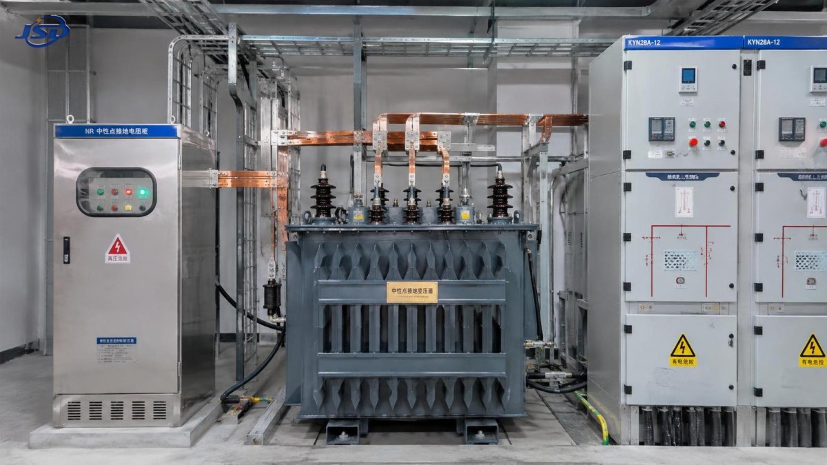
Select the grounding transformer voltage and connection correctly
The neutral grounding transformer must match the system voltage and be suitable for the intended winding connection. Zig-zag grounding transformers are widely used where a neutral point is needed on a three-wire system because they provide a low-impedance path for zero-sequence current while drawing little current under balanced conditions. A wye-delta grounding transformer is another established arrangement, particularly where isolation or specific system integration requirements influence the choice.
The relevant voltage is not just the line-to-line bus rating. The neutral resistor is subjected to approximately line-to-neutral voltage during a ground fault. For a system with nominal line-to-line voltage VLL:
VLN = VLL / √3
The design voltage should reflect the highest system voltage that may be sustained, not merely the nominal value shown on a one-line diagram. Insulation coordination, arrester ratings, temporary overvoltage conditions, and the applicable equipment standard also need review. A grounding transformer installed on a 15 kV class system, for example, must be assessed against the actual maximum service voltage and insulation level required by that system.
When reviewing vendor data, it is important to distinguish between a standard transformer impedance figure and the effective zero-sequence impedance relevant to grounding duty. The latter is the value that affects ground-fault current. The connection, neutral lead arrangement, resistor interface, and any supplied neutral CT should be clearly identified on the approved drawings.
Convert fault-current duty into grounding transformer kVA
The grounding transformer is commonly assigned a short-time kVA rating based on the selected ground-fault current. For a three-phase grounding transformer, a practical rating expression is:
kVA = VLL × IGF / (√3 × 1,000)
Equivalently, because VLN = VLL/√3:
kVA = VLN × IGF / 1,000
Using the 13.8 kV, 400 A example:
kVA = 13.8 × 400 / 1.732 = approximately 3,187 kVA
This does not mean the unit must operate continuously as a 3.2 MVA distribution transformer. It means the grounding transformer must withstand the specified current at the stated voltage for the stated fault duration. Its nameplate should make that duty explicit, such as a defined current or kVA for 10 seconds, 30 seconds, 60 seconds, or continuous operation.
Do not substitute the normal load rating of an associated power transformer for this duty. A grounding transformer may carry negligible current during normal balanced operation, yet be subjected to severe thermal stress during a ground fault.
Time rating is as important as current rating
Grounding equipment is frequently specified for short-time duty because protection is expected to isolate the fault quickly. The correct duration is determined by the complete clearing sequence: relay operating time, breaker opening time, intentional coordination delay, backup protection time, and any credible breaker-failure clearing time. The shortest primary protection operating time is not an adequate basis if the equipment must survive a failed breaker or delayed isolation event.
Thermal duty follows an I²t relationship. A unit selected for a stated current over 10 seconds cannot automatically be treated as suitable for the same current over 60 seconds. Conversely, reducing the fault duration can reduce the required short-time thermal rating, but only if the assumed clearing performance is supported by the protection scheme and project requirements.
Repeated-fault duty also deserves attention. A short-time-rated neutral grounding transformer and resistor need time to cool after a fault. Where the operating philosophy permits reclosing, extended fault investigation, or repeated fault exposure, the thermal assumptions should be documented rather than left implicit.
Check protection sensitivity before fixing the resistor value
The desired fault current must exceed the practical pickup threshold of the protection system with sufficient margin. This review includes relay pickup settings, CT ratio and accuracy, residual-current measurement method, feeder charging current, and coordination with upstream and downstream devices.
A common mistake is selecting the lowest possible fault current to minimize damage, then discovering that feeder relays cannot reliably distinguish a real ground fault from normal unbalance, CT error, or capacitive current. The opposite mistake is selecting a high-resistance-grounding current level based solely on available switchgear withstand capability. Higher current is not automatically better; it may impose a more severe arc-fault condition and increase thermal damage at the fault.
On cable-heavy systems, the aggregate phase-to-ground capacitive charging current requires particular attention. The grounding design must provide a fault current that remains distinguishable from charging current and supports stable ground-fault detection. The relevant method and margin depend on the protection philosophy and the applicable standard or owner specification; it should be confirmed during the protection coordination study rather than assumed from a generic rule.
Grounding transformer impedance must be specified as a limit, not left as a generic catalogue value
Once the target ground-fault current and resistor are selected, calculate the allowable grounding-transformer impedance. If the transformer reactance is too high, the actual current will fall below the protection target. If it is lower than assumed, the current may exceed the intended resistor duty and protection coordination basis.
For preliminary review, impedance is often expressed in per unit or percent on the grounding transformer base:
Zbase = VLL2 / Sbase
The percentage impedance can then be converted to ohms and entered in the zero-sequence study. Because grounding transformer connections affect how sequence quantities are represented, the manufacturer’s impedance data and the study model must use the same basis. A percentage figure without a declared voltage base, kVA base, connection, and sequence meaning is insufficient for final selection.
Also verify whether the manufacturer quotes impedance at rated grounding current, rated kVA, or another condition. This is especially relevant for custom short-time grounding transformers, where the nameplate duty may differ from a conventional continuously rated transformer.
Installation conditions can change the practical selection
Grounding equipment is often installed beside medium-voltage switchgear, within a substation enclosure, or in a dedicated outdoor compartment. Space, ventilation, cable termination access, resistor heat dissipation, neutral conductor routing, and maintenance clearance can all constrain the final arrangement.
Where a packaged substation is being evaluated, the grounding transformer should be treated as a defined part of the grounding scheme rather than as an assumed accessory. For example, an European-Type Compact Substation may be configured for medium-voltage distribution applications, but the evaluator should confirm whether the required grounding transformer, NGR, neutral CT, fault indicator, ventilation provisions, and interconnections are included within the supplied scope or require a separate assembly.
Environmental conditions affect thermal performance. Outdoor enclosures, high ambient temperature, altitude, contamination, and restricted airflow can reduce the available heat dissipation margin. The NGR itself may reach high temperatures during duty, so separation from sensitive cable insulation, control wiring, and enclosure surfaces must be considered. Enclosure IP rating alone does not establish that the resistor and transformer can meet their temperature-rise duty in the installed arrangement.
Documentation that should be requested before approval
A technically complete submittal for a neutral grounding transformer should identify the system voltage, connection type, rated ground-fault current, duty duration, frequency, insulation level, zero-sequence impedance, winding temperature limits, cooling method, terminal arrangement, and applicable test requirements. The NGR documentation should state resistance value, tolerance, current rating, time rating, temperature rise, material, and any monitoring contacts.
Protection documentation should show the calculated minimum and maximum single-line-to-ground fault currents, relay pickup settings, clearing times, CT details, and the assumptions used for source and cable impedances. The review is incomplete if the transformer is rated from a desired current but the network study demonstrates a substantially different current at the protected locations.
The sound selection sequence is therefore to establish the protection objective, model the actual zero-sequence circuit, select resistor resistance, verify the fault-current range, rate the neutral grounding transformer for voltage and short-time kVA, and then confirm thermal and installation suitability. Treating these as separate procurement items without a common calculation basis is the main source of avoidable mismatch in grounding systems.

Get a Quote
Regardless of whether you require general advice or specific support, we are happy to help you.
Send Us Your Inquiry Today

Jinshida Electric remains committed to contributing to global energy development through professional manufacturing and superior service.