





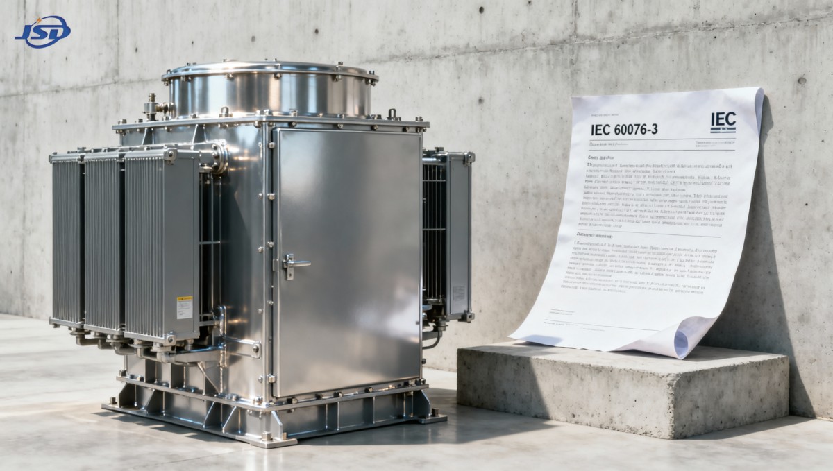
Does 35kv oil immersed distribution transformer tank design meet IEC 60076-3 short-circuit mechanical strength requirements?
Ensuring mechanical integrity under short-circuit conditions is critical for 35kV oil immersed distribution transformer safety and grid reliability. This article evaluates whether standard tank design practices comply with IEC 60076-3 mechanical strength requirements—especially for quality control and safety personnel responsible for certification, inspection, and risk mitigation. Drawing on engineering experience in high-reliability transformer manufacturing, we analyze structural validation methods, common design pitfalls, and real-world test data to support evidence-based compliance decisions.
IEC 60076-3: Core Mechanical Strength Requirements for Tank Design
IEC 60076-3 specifies the mechanical strength criteria that transformer tanks must withstand during sudden short-circuit events. Unlike thermal or dielectric tests, this standard focuses exclusively on dynamic mechanical stress—the transient electromagnetic forces acting on windings, leads, and structural supports—and their transmission to the tank walls, flanges, and mounting structures. For a 35kV oil immersed distribution transformer, the peak short-circuit current may reach 25–40 kA (depending on system impedance), generating radial compression and axial buckling forces that propagate through the core/winding assembly into the tank. The tank itself must resist both inward deformation from vacuum collapse during rapid oil displacement and outward bulging from pressure pulses induced by winding motion.
The standard mandates two primary verification routes: analytical calculation and physical type testing. Analytical verification requires finite element analysis (FEA) modeling of the complete tank structure—including stiffener spacing, plate thickness, gasket compression behavior, and bolt preload distribution—with boundary conditions reflecting actual mounting constraints. Physical testing demands full-scale short-circuit simulation using a dedicated impulse generator, with strain gauges, displacement transducers, and high-speed imaging capturing localized deformation at critical zones: tank corners, manhole frames, radiator mounting brackets, and bushing support plates.
Why Standardized Tank Geometry Alone Is Insufficient
Many manufacturers apply generic tank dimensions derived from legacy designs or catalog templates—e.g., 8 mm side plates with 120 mm × 10 mm vertical stiffeners spaced at 300 mm intervals—for all 35kV units up to 2500 kVA. While such configurations may pass routine hydrostatic pressure tests (per IEC 60076-1), they often fail to satisfy the dynamic load path requirements of IEC 60076-3. Critical oversights include:
- Ignoring the amplification effect of oil column inertia during rapid winding displacement—especially in taller tanks where oil mass contributes significantly to lateral loading;
- Treating flange-to-tank welds as fully rigid joints, whereas real-world fillet welds exhibit measurable rotational compliance under pulsed torque;
- Assuming uniform material yield strength across rolled steel plates, without accounting for cold-work hardening near cut edges or heat-affected zones from welding;
- Using nominal bolt torque values without verifying clamp force retention after thermal cycling or vibration exposure during transport and installation.
These assumptions become especially consequential when transformers operate in distributed solar energy systems, where intermittent fault currents and harmonic-rich waveforms increase cumulative mechanical fatigue. In such applications, a Step-Up Transformer for Photovoltaic Power Stations rated at 35kV/0.69kV must maintain structural integrity not only during utility-side faults but also during inverter-side DC-link failures that induce asymmetric current surges.
Material and Fabrication Variables That Directly Influence Compliance
Steel grade selection plays a decisive role—not just ultimate tensile strength, but more importantly, yield-to-tensile ratio and strain-hardening exponent. S355JO (yield strength ~355 MPa) offers better ductility than S235JR under impact loading, reducing brittle fracture risk at welded corners. However, its higher yield point increases residual stress after forming, demanding strict post-weld stress relief protocols. Plate thickness uniformity is equally vital: ±0.3 mm tolerance is acceptable for static pressure, but ±0.15 mm is required for IEC 60076-3 compliance, as localized thinning below 7.2 mm in a nominally 8 mm plate can initiate plastic hinge formation under pulsed bending moments.
Fabrication sequence matters. Welding stiffeners before final tank assembly introduces internal stresses that redistribute during subsequent machining of mounting holes—altering the effective stiffness matrix used in FEA models. Similarly, painting before testing traps hydrogen at weld interfaces, lowering fracture toughness. Best practice mandates non-destructive testing (NDT) of all full-penetration welds via ultrasonic inspection *before* final surface treatment, with rework performed only using preheated, low-hydrogen electrodes.
Validation Gaps Between Calculation and Reality
Most FEA models assume idealized boundary conditions: perfectly rigid baseplates, zero clearance at lifting lugs, and isotropic material properties. In practice, foundation settlement—even sub-millimeter—decouples the lower tank frame from assumed fixed supports, shifting natural frequencies and resonance modes. Field measurements on 35kV units show that measured strain amplitudes at radiator brackets exceed calculated values by 18–27% when tank feet rest on uneven concrete pads. This discrepancy invalidates many “passing” simulations unless validated against measured modal response data.
Operational Context as a Compliance Determinant
Compliance is not absolute—it depends on application context. A 35kV oil immersed distribution transformer installed indoors with controlled ambient temperature and minimal seismic exposure faces different mechanical demands than one deployed outdoors in coastal regions with salt-laden winds and frequent lightning-induced transients. Corrosion undercutting of stiffener weld toes reduces effective section modulus over time; a unit passing initial type testing may fall outside IEC 60076-3 margins after 8–10 years of service if maintenance neglects visual inspection of corrosion-prone zones. Likewise, radiator replacement with non-OEM units alters mass distribution and damping characteristics—potentially shifting resonant frequencies into ranges excited by harmonic content from renewable energy inverters.
Design Integration Beyond the Tank
Tank strength cannot be isolated from winding support design. Axial forces from short-circuits transfer to the tank via top and bottom clamping structures. If upper yoke clamps rely solely on spring washers without positive-locking nuts, preload loss during thermal expansion allows incremental axial movement—increasing dynamic amplification of tank wall vibration. Similarly, inadequate lead support rigidity permits conductor whip, inducing secondary impact loads on bushing flanges that propagate into adjacent tank sections. These interactions mean that tank compliance verification must include coupled electromagnetic-structural FEA, not standalone tank modeling.
For utility-scale photovoltaic power plants requiring robust grid interconnection, mechanical resilience directly supports long-term harmonic resistance and stable operation under fluctuating generation profiles. Units with verified IEC 60076-3 compliance demonstrate lower incidence of gasket extrusion, reduced oil leakage after repeated fault events, and maintained sealing integrity across thermal cycles—factors that collectively extend service life and reduce lifecycle maintenance costs.
In summary, standard tank geometry for 35kV oil immersed distribution transformers does not automatically meet IEC 60076-3 requirements. Compliance hinges on integrated validation—spanning material specification, fabrication control, boundary-condition realism in simulation, and application-specific operational factors. Relying solely on dimensional conformity or historical precedent introduces unquantified risk. Rigorous, context-aware verification remains essential—not as a certification checkbox, but as a foundational requirement for sustained mechanical integrity.
Hot News
- 00
0000-00
How U.S. DOE efficiency rules affect distribution transformer manufacturers - 00
0000-00
How american type pad mounted transformer seismic qualification affects installation in California utility grids? - 00
0000-00
Do european compact substation transformer EMC compliance tests include conducted emissions up to 30MHz?
0000-00
Contact Us

Get a Quote
Regardless of whether you require general advice or specific support, we are happy to help you.
Send Us Your Inquiry Today

Jinshida Electric remains committed to contributing to global energy development through professional manufacturing and superior service.