





Tap Changer Selection for High-Voltage Transformers Under Variable Loads
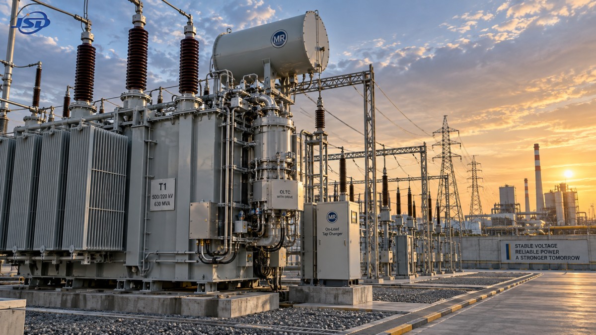
Selecting a high voltage transformer with tap changer is critical when load conditions fluctuate and voltage stability must be maintained across changing operating scenarios.
Technical evaluators should prioritize measurable voltage regulation, switching duty, insulation coordination, control integration, and lifecycle reliability before comparing initial purchase prices.
Start With the Actual Voltage Regulation Requirement
The first selection question is not which tap changer model is available, but how much voltage correction the connected system genuinely requires.
Gather hourly or shorter-interval data for source voltage, transformer loading, feeder voltage, reactive power flow, and downstream equipment sensitivity before defining a range.
A wide tap range may appear safer, yet excessive range can increase mechanical complexity, contact wear, insulation demands, and control coordination challenges.
Evaluate the normal operating band separately from rare contingency conditions, because designing continuous tap operations around exceptional events often produces unnecessary cost.
For many transmission applications, the required regulation range depends on source-side variability, line impedance, load power factor, and transformer impedance characteristics.
Industrial systems require additional attention to motor starting, large rectifier loads, arc furnaces, variable-speed drives, and abrupt process changes.
Renewable-connected substations should account for inverter reactive power control, export limits, curtailment schedules, and voltage changes caused by intermittent generation.
Specify the target controlled voltage, permitted deadband, intended tap range, nominal step voltage, and maximum allowable deviation at critical load points.
Choose Between Off-Circuit and On-Load Tap Changing
The fundamental technology choice is whether taps must change while energized or only when the transformer has been isolated and de-energized.
An off-circuit tap changer suits installations with stable seasonal voltage conditions, infrequent configuration changes, and planned outages acceptable to the owner.
It is mechanically simpler and usually less expensive, but it cannot correct voltage variation during normal energized operation or rapidly changing load periods.
An on-load tap changer, commonly called an OLTC, changes transformer ratios without interrupting load current, making it suitable for dynamic grid conditions.
OLTC selection becomes justified when voltage compliance, process continuity, contractual power-quality obligations, or network stability depends on frequent ratio adjustment.
Technical evaluators should compare expected tap operations per day and year against the manufacturer’s rated mechanical and electrical switching endurance.
Do not assume every fluctuating load needs an OLTC; stable transformer secondary voltage can sometimes be maintained through upstream regulation or reactive compensation.
However, where variable loading persists, a properly specified high voltage transformer with tap changer often prevents recurring undervoltage, overvoltage, and production disruptions.
Match Tap Step Size to System Sensitivity
Tap range defines the total correction capability, while tap step size determines how precisely the transformer can respond to changing voltage conditions.
Smaller steps provide finer regulation, but they can increase the number of transitions needed across the full range and raise operating frequency.
Typical specifications must state the number of positions, percent voltage change per step, total positive range, total negative range, and neutral position.
A large step can cause voltage swings that are unacceptable for sensitive drives, control systems, data equipment, or tightly regulated industrial processes.
Conversely, excessively fine steps may offer little operating benefit where feeder voltage changes slowly and connected equipment tolerates broader voltage variation.
Review the interaction between tap step size and automatic voltage regulator settings, especially the voltage bandwidth, intentional delay, and line-drop compensation values.
The control scheme should avoid repeated oscillation between adjacent positions, commonly called tap hunting, because it shortens mechanical life without improving voltage quality.
Use load-flow studies and time-series simulations to verify that each proposed step produces useful correction under realistic demand and generation conditions.
Evaluate the Load Profile, Not Only the Nameplate Rating
Nameplate MVA establishes a thermal baseline, but tap changer duty is driven by the shape, speed, and repetition of voltage and load changes.
A facility with predictable daytime demand may require only modest operation, while a mine or steel plant can create persistent regulation activity.
Document minimum, average, peak, and ramping load values, together with power factor ranges and the timing of major equipment starts.
Also identify reverse-power periods, because distributed generation or battery discharge may reverse transformer loading and alter voltage-control behavior.
Reverse flow does not automatically prevent OLTC use, but the control logic must remain stable when line-drop compensation changes directional significance.
For renewable projects, assess both rapid irradiance changes and planned dispatch changes, since each may create different voltage-control patterns.
Thermal loading should be examined alongside tap duty, because elevated winding temperature accelerates insulation aging even when voltage regulation remains acceptable.
Request duty calculations that connect the site load profile to estimated annual operations, diverter-switch stress, service intervals, and expected maintenance resources.
Check Insulation Coordination and Dielectric Margins
Tap changer selection is inseparable from transformer insulation design, particularly at high voltage where transient stresses can exceed normal operating voltages significantly.
The evaluation should include rated lightning impulse withstand level, switching impulse requirements, power-frequency withstand voltage, creepage distance, and site pollution severity.
Tap leads, selector contacts, diverter compartments, and transition resistors must withstand expected electrical stress across every permissible tap position.
Higher altitude reduces air insulation performance, so projects above standard reference altitude require derating or appropriately adjusted external insulation clearances.
Coastal, desert, and heavily contaminated industrial sites need careful attention to bushings, enclosures, sealing systems, and external tracking resistance.
Where transformer oil is used, confirm oil quality control, moisture limits, dielectric testing procedures, and separation arrangements for OLTC oil compartments.
Vacuum-type OLTC technologies can reduce oil contamination concerns in certain designs, but suitability still depends on duty, voltage class, service support, and specification requirements.
A robust dielectric review protects against failures that are infrequent but consequential, including flashover, insulation breakdown, internal arcing, and forced transformer replacement.
Specify Controls, Monitoring, and Protection as One System
A tap changer cannot be evaluated independently from its automatic voltage regulator, protection relays, supervisory controls, and site communications architecture.
The voltage regulator should provide configurable setpoints, bandwidth, time delay, operation limits, local and remote modes, event records, and alarm functions.
Line-drop compensation can improve remote voltage control, but incorrect settings may cause overcorrection when feeder impedance or power-flow direction changes.
Parallel transformers need coordinated control to prevent circulating current, unequal loading, and unnecessary tap movement between units sharing a busbar.
Specify master-follower, circulating-current, or reactive-power compensation methods according to the transformer arrangement and operational philosophy of the installation.
Condition monitoring should include tap position, motor-drive operating time, operation counts, oil condition where applicable, temperature, and abnormal switching alarms.
For digitally managed facilities, request communication compatibility with existing SCADA or energy-management platforms using suitable protocols and cybersecurity controls.
Battery-connected sites may benefit from coordinated controls; the 500kW/1MWh Air Cooling Container Energy Storage System supports common industrial integration scenarios through intelligent battery management and optional EMS functions.
Assess Reliability Through Design Details and Serviceability
Reliability claims should be supported by verifiable design information, documented tests, maintenance intervals, failure records, and accessible service arrangements.
Ask whether the diverter switch uses oil, vacuum, or another interruption method, and understand the resulting inspection and consumable replacement requirements.
Motor-drive mechanisms deserve close examination because worn gears, limit switches, contactors, and control wiring can cause unavailable or incorrect tap movement.
Review the enclosure rating, corrosion protection, heater arrangements, gasket materials, and condensation control for the actual climate and installation location.
Maintenance access matters in practice; technicians must safely inspect the drive, sample oil where relevant, replace components, and confirm position indication.
Require clear documentation for routine inspection, alarm response, emergency manual operation, recommended spare parts, and post-fault diagnostic procedures.
Factory acceptance testing should cover ratio verification, functional tap operations, control interlocks, insulation tests, wiring checks, and protection interface confirmation.
For critical substations, consider onsite commissioning support, baseline condition measurements, training, and long-term access to qualified parts and technical assistance.
Use Lifecycle Cost Instead of Purchase Price Alone
The lowest initial quotation may create higher lifetime expense if it leads to excessive maintenance, poor voltage performance, process losses, or unavailable spare parts.
Compare alternatives using installed cost, expected energy losses, maintenance labor, outage risk, spares, monitoring capability, and projected operational life.
Voltage regulation has economic value when it prevents motor overheating, equipment trips, rejected production, unnecessary reactive power penalties, and premature component failure.
Energy efficiency should include transformer no-load and load losses, since a tap changer cannot compensate for an inefficient core or unsuitable winding design.
Evaluate whether the proposed unit supports future capacity expansion, changed generation patterns, parallel operation, and revised voltage-control objectives without replacement.
A modular energy-storage system can also influence future operating profiles by shifting demand, supporting backup power, or absorbing renewable generation during constrained periods.
When considering such integration, confirm protection coordination, transformer thermal capacity, harmonic performance, and control priorities before assuming storage reduces tap duty.
Financial evaluation is strongest when technical assumptions are explicit, traceable to measured data, and tested against credible operating scenarios rather than optimistic averages.
Build a Defensible Technical Selection Process
A defensible selection begins with a site data package containing network studies, voltage history, load profiles, protection requirements, environmental conditions, and expansion plans.
Translate that information into a specification covering rated voltage, MVA, vector group, impedance, tap range, steps, control accuracy, and duty expectations.
Require suppliers to state assumptions clearly, including reference standards, ambient conditions, altitude, cooling mode, permissible overload, and estimated tap operation capability.
Evaluate deviations carefully because seemingly minor differences in regulation range, insulation level, control functions, or maintenance scope can change project risk materially.
Use a weighted technical comparison rather than a price-only spreadsheet, assigning meaningful value to reliability, maintainability, compatibility, and verified test evidence.
During clarification, ask suppliers to explain how their proposed configuration responds to low load, peak load, reverse flow, contingency voltage, and control failures.
The final decision should demonstrate that the transformer will maintain voltage within limits while remaining mechanically durable and operationally manageable throughout its intended service life.
In summary, selecting a high voltage transformer with tap changer under variable loads requires system-based analysis, not isolated equipment comparison. Correctly matched regulation, duty, insulation, controls, and service support create dependable long-term voltage performance.

Get a Quote
Regardless of whether you require general advice or specific support, we are happy to help you.
Send Us Your Inquiry Today

Jinshida Electric remains committed to contributing to global energy development through professional manufacturing and superior service.