





Three-Phase High-Voltage Transformer Connections Explained: Delta vs. Wye
When a medium- or high-voltage distribution design reaches the transformer connection decision, Delta and Wye are often treated as interchangeable line-diagram options. They are not. The selected winding connection changes how the system is grounded, what voltage each winding must withstand, how unbalanced loads behave, and what happens during a line-to-ground fault. A connection that works well for an isolated industrial motor bus may create avoidable protection or voltage-reference problems when applied to a grounded facility distribution network.
For a three phase high voltage transformer, the practical starting point is simple: choose Wye where a stable grounded neutral, phase-to-neutral utilization, or reduced winding insulation stress is required; choose Delta where three-wire service, harmonic containment, tolerance of certain unbalanced conditions, or a closed path for zero-sequence and triplen harmonics is more useful. The final decision must consider both the high-voltage and low-voltage sides together, not each winding in isolation.
The connection changes more than the nameplate voltage
Three-phase transformers commonly use Delta (Δ) and Wye (Y) winding arrangements on either side. A Delta winding connects its three phase windings end-to-end in a closed loop. A Wye winding joins one end of each phase winding at a common neutral point. That neutral may be solidly grounded, impedance-grounded, grounded through a reactor, or left ungrounded depending on the system design.
The line-to-phase voltage relationship is the first engineering difference:
- In a Wye connection, line voltage equals phase voltage multiplied by √3. Each winding therefore sees only line-to-neutral voltage.
- In a Delta connection, line voltage equals phase voltage. Each winding is exposed to the full line-to-line voltage.
This affects insulation coordination directly. On a 13.8 kV Wye winding, an individual phase winding is designed around 13.8/√3 kV to neutral, while a 13.8 kV Delta winding phase sees 13.8 kV. The complete insulation design still depends on impulse level, grounding method, surge protection, and system overvoltage studies, but the phase-voltage relationship is a major reason Wye windings are often attractive at higher voltages.
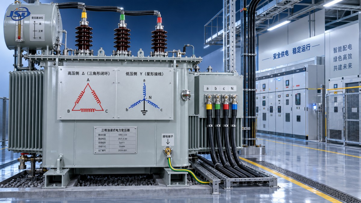
Connection notation also matters. A designation such as Dyn11 indicates the high-voltage winding is Delta, the low-voltage winding is Wye with neutral brought out, and the clock number identifies the phase displacement. The vector group is not a catalog detail: it determines whether transformers can be paralleled and whether downstream relay settings, metering, and phase-sensitive loads will see the expected phase relationship.
Where Wye connection solves a real system problem
A grounded Wye secondary is often selected because the downstream network needs a reliable reference to earth. This is typical where a facility supplies line-to-neutral loads, requires controlled ground-fault protection, or distributes power through four-wire systems. The neutral provides a defined return path for single-phase loads and permits phase-to-neutral voltage to be used without installing a separate grounding transformer.
Consider a site where a transformer feeds lighting panels, controls, small auxiliary loads, and larger three-phase equipment. A Wye secondary can provide both line-to-line and line-to-neutral utilization voltages, provided the secondary rating and load plan support it. The neutral should not be assumed to be unlimited; its conductor sizing, grounding arrangement, fault-duty rating, and expected harmonic current all require review.
On the high-voltage side, a Wye connection can reduce the voltage stress across each phase winding. That can be valuable when insulation economy and high-voltage winding design are important. A grounded Wye high-voltage winding also gives the upstream protection system a predictable zero-sequence path. However, that benefit is only desirable when it matches the intended grounding philosophy. A solidly grounded primary may increase available ground-fault current seen by upstream equipment. An impedance-grounded neutral may limit that current, but then neutral equipment, relay coordination, and temporary overvoltage performance need coordinated engineering.
Wye is not automatically the “safer” connection. An ungrounded Wye system can develop unstable phase-to-ground voltages during a ground fault. On a system with significant cable capacitance, intermittent arcing faults can create overvoltages that place stress on insulation and surge arresters. The question is not merely whether the winding is Wye; it is whether the neutral is accessible and how it is intentionally grounded.
What Delta contributes to transformer performance
Delta is often chosen where a three-wire system is appropriate and no neutral load is required. Its closed loop provides an internal circulating path for triplen harmonics—particularly third-harmonic components generated by transformer magnetizing current. Without a suitable path, those harmonic voltages can distort phase-to-neutral waveforms in Wye-connected systems. A Delta winding can help stabilize the waveform and keep these components from appearing as line currents on the other side.
The closed Delta also changes zero-sequence behavior. Zero-sequence currents associated with line-to-ground faults can circulate within a Delta winding but do not normally pass as line currents through it to the other side. This characteristic can be useful for isolating ground-fault effects between systems. It can also surprise a protection engineer who expects a primary ground relay to detect every secondary ground fault. Relay schemes must be based on the actual transformer vector group and grounding paths, not on a simplified one-line diagram.
Delta can tolerate certain unbalanced load conditions well because the closed winding helps balance internal magnetic effects. In some utility and industrial arrangements, an open-Delta bank may be used temporarily after one transformer unit is removed from a three-unit Delta bank. That arrangement has materially reduced capacity and is not a general substitute for a full three-unit bank. Technical evaluations should confirm whether contingency operation is truly part of the requirement rather than treating open-Delta capability as a standard design advantage.
A Delta secondary has no inherent neutral. A neutral can be created downstream using a grounding transformer or other designed grounding arrangement, but that adds equipment and must be evaluated as a system. It is not appropriate to improvise a neutral connection from a Delta corner or to ground a point that was not designed for that duty.
Common connection pairs and the decisions behind them
Delta–Wye is widely used when a higher-voltage three-wire feeder supplies a lower-voltage facility distribution system that needs a grounded neutral. The Delta primary blocks direct transfer of zero-sequence current from the secondary to the source, while the Wye secondary gives the load side a defined ground reference. This does not eliminate ground-fault current; it shapes where the fault current flows and which protective devices should respond.
Wye–Delta can be appropriate where the incoming high-voltage system grounding arrangement supports a Wye primary and the output serves only three-phase loads. A motor bus may be a candidate, but “motor load” alone is not enough to decide. Variable-frequency drives, harmonic filters, capacitor banks, maintenance connections, and future auxiliary loads can all introduce grounding and harmonic requirements that change the preferred arrangement.
Evaluate fault behavior before approving the vector group
A transformer connection should be reviewed against credible fault scenarios, especially single line-to-ground faults. The study should establish the fault-current path from the source through transformer windings, neutral grounding equipment, metallic return paths, and protective devices. The magnitude of current determines more than breaker interrupting duty. It affects relay sensitivity, arc-flash calculations, touch-voltage risk, equipment thermal withstand, and the ability to locate a fault selectively.
For grounded-Wye systems, confirm the neutral grounding method and rating. Solid grounding may provide high fault current that supports rapid overcurrent operation. Resistance grounding may limit damage and arc-flash energy but generally requires sensitive ground-fault relays and a defined operational response to the first fault. Reactance grounding has its own tradeoffs in fault current and transient overvoltage. The transformer neutral bushing, neutral conductor, grounding resistor or reactor, and protective devices must be rated as a coordinated assembly.
For Delta systems, do not assume the absence of a neutral means the absence of ground-fault consequences. A first ground fault on an ungrounded or impedance-grounded distribution system may not produce enough current for ordinary phase overcurrent devices to operate. Detection may depend on insulation monitoring, residual-voltage methods, or dedicated ground-fault relays. Continued operation after an alarm may be permissible only under an established operating procedure; a second fault on another phase can become a phase-to-phase fault with much higher energy.
Voltage regulation, load type, and harmonics
Connection choice does not replace a proper voltage-regulation calculation. Transformer impedance, source impedance, conductor length, motor-starting current, power factor, and load step size determine the voltage seen at equipment terminals. Still, winding connection influences how unbalanced and nonlinear load currents are handled, which can matter in facilities with mixed load profiles.
Wye secondaries serving substantial single-phase nonlinear loads may experience neutral harmonic current, especially from triplen harmonics that are in phase in all three phases and therefore add in the neutral. This calls for an assessment of expected load spectrum, neutral capacity, temperature rise, and whether filtering or load distribution is needed. A Delta winding on the opposite side may provide a circulation path for some triplen components, but it should not be treated as a cure for poor load allocation or an undersized neutral.
Where the transformer supports equipment with a power-electronic interface, the transformer decision should be coordinated with the converter’s grid requirements. For example, an outdoor energy storage installation may connect at 380 V or 400 V and require a stable, properly grounded AC source for protection and control functions. The 125kW/261kWh Commercial & Industrial Energy Storage System is specified with 380 V / 400 V AC output and may be used for peak shaving, load shifting, backup support, or renewable-energy integration. Its upstream transformer and switchgear arrangement should be selected according to the facility’s grounding scheme, available fault level, parallel operating plan, and applicable interconnection requirements—not simply because a Delta or Wye label appears familiar.
A practical review sequence for technical evaluation
Begin with the loads rather than the transformer catalog. Identify whether the secondary must serve phase-to-neutral loads, whether a neutral is required for control circuits, and whether the load mix is predominantly balanced three-phase, substantially single-phase, or nonlinear. Then identify the upstream grounding system and the desired downstream grounding method. These two items usually narrow the connection options quickly.
- Confirm nominal voltages on both sides, including maximum operating voltage and required taps. Distinguish line-to-line ratings from phase-to-neutral utilization voltage.
- Define the neutral requirement. State whether the neutral is for load service, system grounding, fault detection, or a combination of these functions.
- Review ground-fault paths for faults on either side of the transformer. Verify which relays see zero-sequence current and which devices are expected to clear the fault.
- Check the vector group against all transformers that may parallel now or later. Matching voltage ratio alone is insufficient; phase displacement, impedance, tap position, and polarity must also be compatible.
- Assess nonlinear loads, expected unbalance, capacitor banks, drive systems, and sensitive electronics. Decide whether a Delta tertiary or another harmonic-control measure is justified.
- Verify insulation levels, surge arrester placement, neutral insulation duty, and the grounding equipment rating against the selected topology.
One recurring mistake is selecting a grounded Wye secondary solely because it is convenient for general distribution, then later using it to parallel a Delta-connected source or a transformer with a different clock designation. Another is selecting Delta–Delta for a motor-focused installation without accounting for future controls, service receptacles, monitoring equipment, or energy storage interfaces that require a clear voltage reference. Both issues are easier to resolve during design than after switchgear, cable systems, and relay panels are installed.
When a tertiary winding deserves attention
A tertiary Delta winding is sometimes included on a Wye–Wye transformer to provide a path for third-harmonic and zero-sequence currents, stabilize the magnetic circuit, or supply an auxiliary load. Its presence can materially affect fault studies and protection behavior. A tertiary should not be regarded as an unused extra winding: its voltage rating, loading limit, grounding status, surge protection, and connection to any auxiliary system all matter.
Where a tertiary is not externally loaded, its internal harmonic duty can still be relevant to thermal design. Where it is externally connected, the added load and possible fault contribution must be included in the system model. Technical documentation should clearly show whether the tertiary is Delta, Wye, grounded, or isolated, rather than leaving it as an ambiguous symbol on a single-line drawing.
Questions that often arise during review
Can a Delta secondary supply single-phase loads?
It can supply line-to-line single-phase loads, but it does not inherently supply phase-to-neutral loads because no neutral point exists. Adding a grounding transformer may establish a reference for grounding purposes, yet that does not automatically create a full-capacity neutral for ordinary load service.
Does a Wye connection always require grounding?
No. A Wye winding may be ungrounded, but its neutral behavior must be intentionally designed. Leaving the neutral ungrounded can complicate ground-fault detection and allow phase-to-ground voltage displacement during faults. Whether it is acceptable depends on the system grounding philosophy and protection scheme.
Can transformers with different vector groups operate in parallel?
Usually not without a specifically engineered arrangement. Different phase displacement groups can create circulating currents or effectively impose a fault between transformer outputs. Ratio, impedance, polarity, tap settings, phase sequence, and vector group all need to be compatible before paralleling.

Get a Quote
Regardless of whether you require general advice or specific support, we are happy to help you.
Send Us Your Inquiry Today

Jinshida Electric remains committed to contributing to global energy development through professional manufacturing and superior service.