





Which routine test reports should a distribution transformer manufacturer provide?
Before releasing a distribution transformer for shipment or installation, request a serial-number-specific routine test report covering winding resistance, voltage ratio and phase displacement, no-load loss and current, load loss and short-circuit impedance, and the applicable dielectric tests. A distribution transformer manufacturer should also document any additional routine checks required by the transformer design, governing standard, and purchase specification.
A certificate stating “tested and passed” is not enough to resolve a shipment hold when the delivered nameplate differs from the approved drawing or the reported losses lack a reference temperature. Acceptance depends on traceable measurements, defined test conditions, and identifiable acceptance criteria—not simply a compliance declaration.
Establish the required test scope before reviewing results
Start with the purchase order, approved technical schedule, transformer nameplate data, and specified standard editions. These documents determine which tests are routine, which are design or type tests, and which require a separate agreement. A consolidated factory report is acceptable; each test does not need its own certificate, provided the results remain individually identifiable.
For IEC-based projects, IEC 60076-1 provides general transformer requirements, while IEC 60076-3 addresses insulation levels and dielectric tests. Dry-type transformers also require reference to IEC 60076-11 where applicable. IEEE-based projects commonly use IEEE C57.12.00 and IEEE C57.12.90 for liquid-immersed equipment, with different documents applying to dry-type equipment. Do not transfer test classifications or tolerances between these systems without checking the contractual requirements.
The applicable standard is not the entire acceptance specification. Guaranteed losses, impedance, tap arrangements, efficiency obligations, and documentation requirements may be more specific in the contract. Resolve conflicts before testing rather than choosing whichever requirement makes a result appear acceptable.
The core routine records and what they should contain
Winding resistance: temperature and terminal labels matter
A resistance figure without temperature information has limited acceptance value. Conductor resistance changes with temperature, so apparently different readings may reflect different thermal conditions rather than a winding defect. The report should identify whether values are measured or corrected and explain the temperature basis used.
Compare readings only after accounting for winding connection and measurement configuration. Line-to-line measurements on a delta winding cannot be interpreted like individual phase measurements on an accessible star winding. An unexplained discrepancy should trigger review of terminal identification, tap position, connection diagrams, and measurement stability before it is classified as a manufacturing fault.
Ratio and vector group: confirm the intended connection
Voltage-ratio testing verifies the relationship between windings; phase-displacement or polarity checks verify how those windings are connected. Both are important when equipment will operate in parallel or connect to an existing distribution system.
Request results for every tap position required by the governing procedure, not just a nominal-ratio statement. Check that tap numbering matches the nameplate and approved drawings. A technically plausible ratio can still represent the wrong tap arrangement, while a correct ratio alone does not establish the correct vector group.
Losses and impedance: compare on the same basis
No-load loss and current should be associated with the specified applied voltage and frequency. Waveform effects and the measurement method can influence results, so any corrections required by the governing procedure should be identifiable. Do not compare a result obtained under different excitation conditions directly with the guaranteed value.
Load loss and short-circuit impedance require equally careful handling. Look for the test current, reference power base, tap position, measurement temperature, and temperature-corrected results. The specified reference temperature depends on the transformer and governing requirements; it should not be assumed from another project’s report.
Impedance affects fault-current calculations and parallel operation. If the reported value differs from the approved schedule, engineering review may be necessary even when the manufacturer considers it within a standard tolerance. Contractual guarantees and system-design assumptions must both be addressed.
Dielectric documentation needs more than “withstand: pass”
The dielectric section should identify the tests actually performed, rather than grouping everything under “high-voltage test.” Applied-voltage and induced-voltage tests stress insulation differently. Depending on the design and applicable requirements, other dielectric tests may also belong in the agreed schedule.
For each applicable test, request the test level, duration, terminal arrangement, and result. Induced-voltage records should include the relevant frequency and duration basis. Where partial-discharge measurement is required, the report should include the measured quantity, test conditions, and acceptance limit—not merely a check mark.
Do not treat lightning impulse testing as universally routine. Its classification and applicability depend on the governing standard, insulation category, and equipment specification. Likewise, partial-discharge testing is part of routine testing for applicable dry-type transformers under IEC requirements, but should not be imposed indiscriminately on every liquid-immersed distribution transformer.
Insulation resistance may be useful and may be contractually required, but it does not replace prescribed dielectric withstand tests. A high insulation-resistance reading cannot demonstrate that every required insulation stress test has been completed.
Verify that the report belongs to the delivered unit
Before judging the numbers, establish identity. Compare the report’s serial number with the physical nameplate, packing list, and release documentation. Confirm rated power, winding voltages, frequency, vector group, cooling designation, and tap range. A report for an identical model is not evidence that the delivered transformer passed its unit-specific tests.
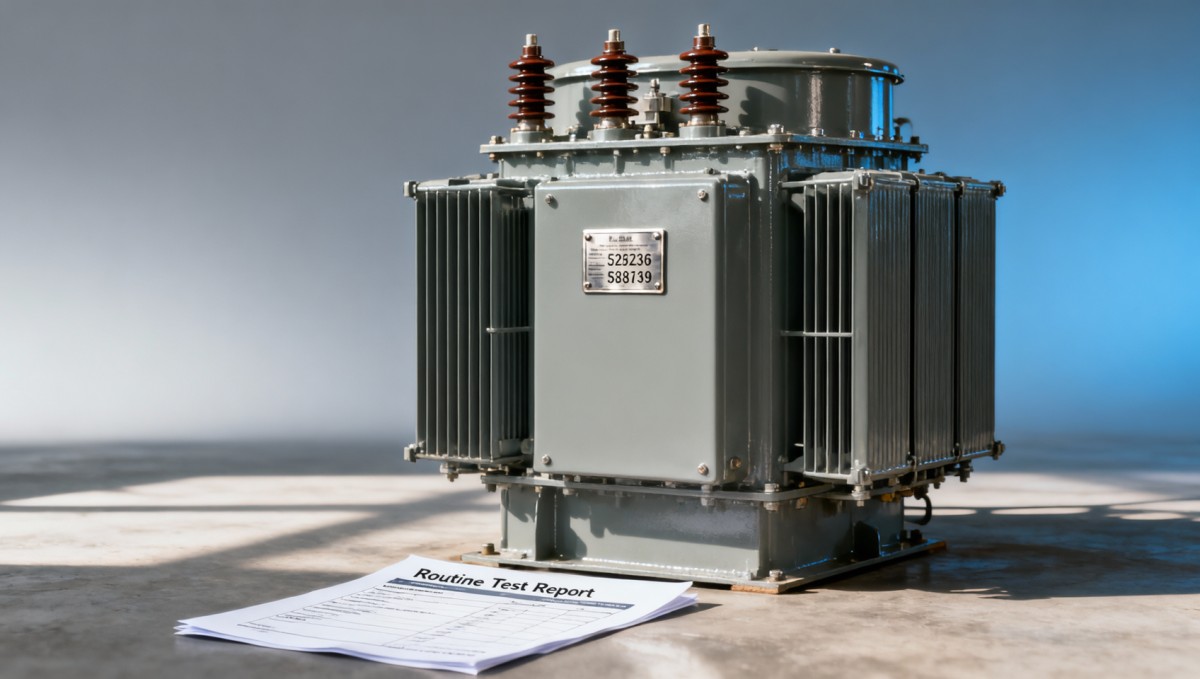
The report should also identify the manufacturer and testing location, test date, report number, applicable standards, and approval authority. Test equipment should be traceable through instrument identifiers and calibration records, either within the report or through supporting records available for review. Every calibration certificate need not be attached unless the contract requires it, but traceability should be demonstrable.
- Separate measured and calculated data. Corrected losses and derived impedance values should not appear indistinguishably beside raw readings.
- Require an acceptance basis. Results should be assessable against the applicable limits and guarantees, whether these appear in the report or a referenced approved schedule.
- Control revisions. A corrected report should identify its revision and supersede the earlier version without obscuring why it changed.
- Explain retests. When repair, adjustment, or rework precedes retesting, request the disposition and justification for the repeated test scope.
A witness signature confirms attendance within the stated scope; it does not automatically prove that all contractual tests were performed. Review witness records alongside the actual results and inspection plan.
Additional records depend on the transformer construction
Liquid-immersed units may require routine tank tightness or pressure-related checks under the applicable specification. The record should identify the method, conditions, and outcome. Oil-quality reports may also be required for the supplied insulating liquid, but a fluid batch certificate is not interchangeable with the transformer’s electrical routine test report.
For dry-type units, verify the applicable partial-discharge requirements and the insulation-system information needed to interpret the test schedule. Temperature-rise evidence generally belongs to type or design verification rather than an automatic repeat test on every unit; the classification must follow the selected standard.
Where fitted, tap changers, built-in current transformers, accessible core and frame insulation, alarms, fans, and protective devices can introduce additional checks. Some are routine requirements under a particular standard; others are functional or contractual inspections. Require the manufacturer to identify the basis instead of silently omitting a test because the report template lacks a field.
A packaged substation requires more than the transformer report
When the transformer is supplied inside a prefabricated assembly, establish separate documentation boundaries for the transformer, high-voltage equipment, low-voltage assembly, and completed package. A transformer routine test report does not establish the performance of switchgear interlocks, protective circuits, assembly wiring, or enclosure construction.
For example, the European-Type Compact Substation is offered with transformer capacities from 100 kVA to 2500 kVA and configurable high- and low-voltage arrangements. Its acceptance dossier should connect the installed transformer’s serial number to the package identification and include the applicable component and assembly verification records.
Confirm enclosure protection ratings for the exact supplied configuration and compartment, rather than selecting a rating from a general product description. Similarly, a list of standards or conformity marks does not replace the test evidence required for the ordered assembly.
Resolve documentation gaps before authorizing release
- Build a requirement-to-evidence register. List each required test, its contractual or standards basis, the relevant report reference, and any unresolved deviation.
- Classify the gap. A missing signature is different from an omitted dielectric test, an incorrect serial number, or a measured value outside the acceptance limit.
- Request a specific correction. Ask for the missing temperature basis, tap results, test conditions, or traceable source record rather than requesting a generic “updated certificate.”
- Route technical deviations for disposition. Values outside agreed limits, changed insulation test levels, or mismatched ratings require authorized engineering review, not administrative editing.
- Close the release hold against evidence. Retain the approved report revision and documented resolution with the shipment or installation acceptance record.
Missing documentation does not by itself prove a transformer is defective, but it leaves acceptance unsubstantiated. Where original records cannot establish compliance, any repeat testing should follow an agreed procedure and the applicable standard’s provisions for previously tested equipment. Unplanned repetition of high-voltage tests is not a harmless paperwork remedy, and site insulation checks should not be treated as a substitute for missing factory routine tests.

Get a Quote
Regardless of whether you require general advice or specific support, we are happy to help you.
Send Us Your Inquiry Today

Jinshida Electric remains committed to contributing to global energy development through professional manufacturing and superior service.