





What industrial furnace transformer cooling failure symptoms precede catastrophic winding damage?
What Industrial Furnace Transformer Cooling Failure Symptoms Precede Catastrophic Winding Damage?
For maintenance technicians overseeing smelting lines, arc furnaces, or induction heating systems, an industrial furnace transformer isn’t just another asset—it’s the thermal and electrical linchpin of production. When cooling fails, downtime isn’t measured in hours; it’s measured in lost batches, rework, safety investigations, and unplanned capital expenditure. The critical insight—often missed until it’s too late—is that catastrophic winding failure rarely occurs without warning. It’s preceded by a cascade of measurable, observable, and often reversible symptoms. This article cuts past generic thermal theory to focus on what you see, hear, measure, and log *in the field*—and how to interpret those signals before insulation degradation crosses the point of no return.
Hotspot Temperature Rise: The First Reliable Canary
Oil temperature gauges and winding thermocouples are standard—but their value lies not in absolute readings, but in deviation from baseline under identical load profiles. A consistent 8–10°C rise in hotspot temperature (measured via fiber-optic probes embedded near the top of LV windings) over three consecutive shifts, with no change in ambient conditions or load, is the strongest early indicator of compromised cooling. This isn’t about exceeding nameplate limits; it’s about *drift*. In ONAN/AN-cooled units—common in metallurgy applications—this drift most often stems from partial oil flow obstruction (sludge buildup in radiators), degraded oil oxidation stability (acid number >0.1 mg KOH/g), or air pockets trapped in high-point coolers. Crucially, this symptom appears *before* alarms trigger. If your DCS shows repeated “high winding temp” alerts only during peak load, but trending data reveals a steady upward slope even at 60% load, treat it as confirmed cooling degradation—not a transient event.
Abnormal Oil Flow Behavior: Not Just “Low Flow”
Flow meters on forced-oil circuits (AN or OFAF variants) are often misinterpreted. A reading within nominal range doesn’t guarantee effective heat transfer. Look instead for *variance*: inconsistent flow rates across parallel radiator banks, or flow dropping more than 15% between cold-start and stabilized operation. That drop suggests internal restriction—typically oxidized sludge accumulating in narrow oil passages or cooler tube headers. Also monitor pressure differentials across oil filters and coolers. A delta-P increase of >25% from commissioning values, especially when accompanied by rising oil temperature, points directly to fouling—not pump failure. Note: many furnace transformers operate intermittently, allowing sludge to settle during off-cycles. This makes flow anomalies *more* pronounced at startup than during steady-state operation.
Inconsistent Winding Resistance Readings: A Red Flag for Localized Overheating
DC resistance testing is routine—but its diagnostic power is underused. A shift of >2% in phase-to-phase resistance imbalance (e.g., RAB vs. RBC) over six months, with no rewinding or tap-changer adjustment, strongly indicates localized hotspots altering copper resistivity. More telling is *directional drift*: if RAB consistently increases while RBC remains stable across multiple tests, suspect uneven cooling affecting one winding section—often due to blocked ducts or misaligned oil deflectors. This isn’t noise. It’s evidence of thermal stress concentrating where cooling is weakest. For rectifier-fed loads, harmonics exacerbate this effect, making resistance imbalance an especially sensitive early marker.
Alarm Patterns That Matter—And Those That Don’t
“High oil temp” and “winding overtemp” alarms are expected during heavy-duty cycles. What matters is *pattern*, not frequency. Persistent “cooling fan fault” alarms—even after fan reset—that recur within 48 hours suggest underlying issues: motor bearing wear (causing reduced airflow), voltage imbalance across fan supplies, or control logic errors triggered by false temperature signals. More critically, repeated “oil level low” alarms followed by quick recovery often indicate oil expansion/contraction due to thermal cycling *without proper breathing*, leading to moisture ingress and accelerated paper aging. These aren’t isolated faults—they’re system-level clues pointing to cooling inefficiency cascading into insulation deterioration.
Why Copper Windings Change the Risk Profile
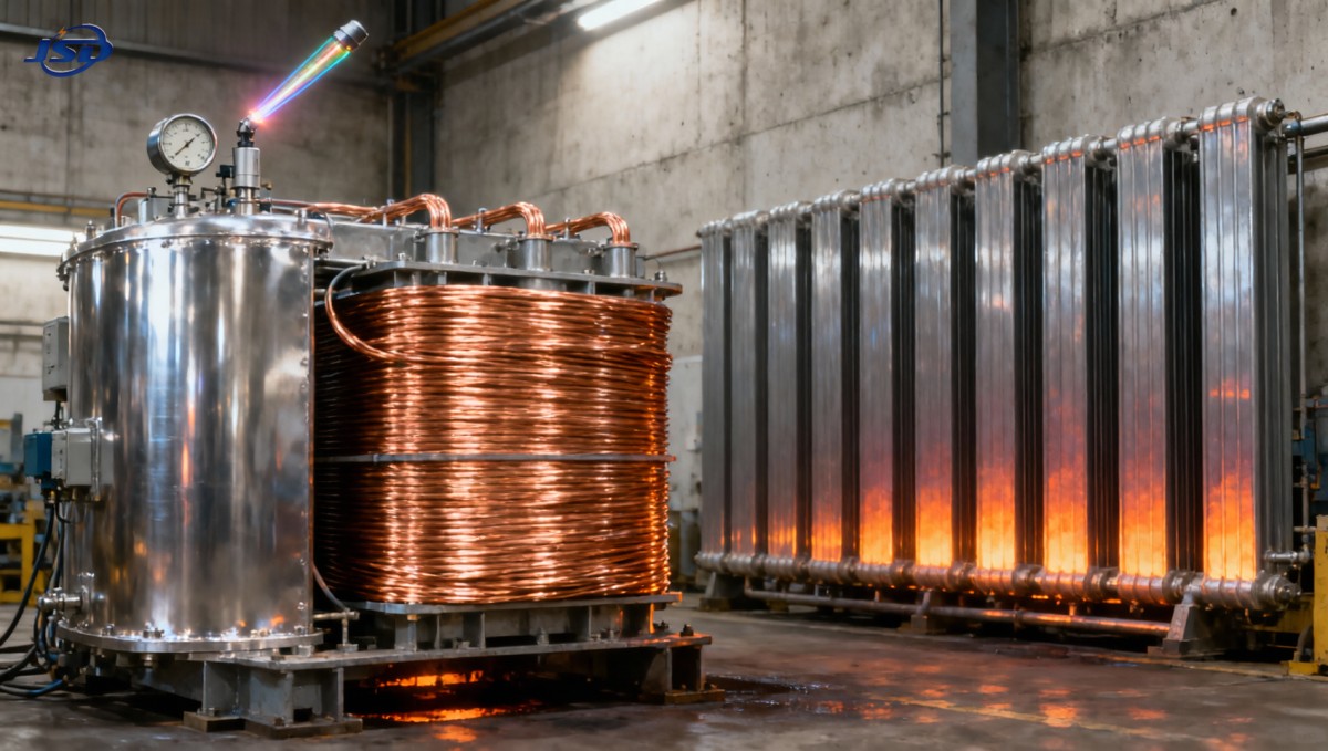
Copper’s superior thermal conductivity and lower resistivity mean furnace transformers run cooler *for the same kVA rating*—but also make them less tolerant of cooling degradation. A 5% reduction in oil flow causes a proportionally larger hotspot rise in copper-wound units versus aluminum, because copper’s higher density concentrates heat faster where convection fails. That’s why Isolation and Rectifier Special Transformer models built for metallurgy and electrolysis specify 100% copper windings: not just for efficiency, but to ensure predictable, linear thermal response—making early deviations easier to spot and correlate. Their design includes optimized duct spacing and oil flow paths calibrated for intermittent, high-peak loads—reducing the likelihood of localized stagnation.
When to Intervene—And What Action Actually Stops Progression
Do not wait for alarm thresholds. At first sign of trending hotspot rise (>5°C above baseline over 2 weeks), initiate a targeted inspection protocol:
- Verify oil condition: Test dielectric strength, acid number, and interfacial tension—not just moisture content. Oxidized oil loses cooling capacity long before breakdown voltage drops.
- Inspect radiator surfaces: Not just for debris, but for *uneven thermal gradients* using IR imaging. Cold spots indicate blocked tubes; hot spots indicate oil bypassing sections.
- Check oil flow distribution: Use ultrasonic flow probes at individual radiator inlets—if variance exceeds ±10%, clean or replace affected banks.
- Review load history: Correlate temperature spikes with actual harmonic content (not just RMS current). High THD loads accelerate hotspot formation where cooling is marginal.
Flushing oil alone rarely solves the root cause. Sludge removal must be followed by flow path verification and, if resistance imbalance persists, targeted thermal scanning to locate developing hotspots before insulation carbonization begins.
The Bottom Line for Uptime-Critical Operations
Catastrophic winding failure in an industrial furnace transformer is almost always a failure of detection—not design. The symptoms described here appear weeks, sometimes months, before insulation loss becomes irreversible. They demand attention not as “minor anomalies,” but as direct evidence of thermal stress accumulating where cooling is compromised. Your most valuable tool isn’t a new sensor—it’s disciplined trending of existing measurements against verified baselines, interpreted through the lens of real-world furnace load patterns. When cooling degrades, copper windings don’t fail silently. They signal clearly—if you know what deviation looks like.

Get a Quote
Regardless of whether you require general advice or specific support, we are happy to help you.
Send Us Your Inquiry Today

Jinshida Electric remains committed to contributing to global energy development through professional manufacturing and superior service.