





What happens when single phase transformer supplies unbalanced three-phase loads without neutral connection?
What happens when a single phase transformer supplies unbalanced three-phase loads without neutral connection? The short answer is: it doesn’t work as intended — and the consequences aren’t subtle. Voltage distortion, thermal stress, unexpected tripping, and premature insulation failure are not hypothetical risks. They’re documented outcomes in real substations, industrial feeders, and rural distribution points where this configuration has been misapplied.
This isn’t about theoretical edge cases. It’s about what an operator sees on the panel: one phase reading 430 V while another drops to 360 V; a transformer humming louder than usual with oil temperature creeping past 85 °C; motors overheating on Line B while Line C remains cool; protective relays flagging “unbalanced voltage” alarms that reset only to reappear minutes later. These symptoms point to a fundamental mismatch — using a single phase transformer to serve a three-phase system *without* a neutral return path.
Why This Setup Breaks Basic Three-Phase Physics
A three-phase load — especially an unbalanced one — relies on two things to maintain stable voltages at the load terminals: (1) a closed path for zero-sequence current, and (2) balanced source impedance across all phases. A single phase transformer has neither.
When you connect, say, a 230 V single phase transformer between Phase A and Phase B of a 400 V three-phase system (a common but flawed workaround), you’re not “feeding one leg” — you’re forcing Phase A and Phase B to share a common magnetic circuit while Phase C floats entirely. There’s no reference to neutral, no path for third-harmonic or zero-sequence currents generated by non-linear loads (like variable frequency drives or LED lighting), and no way for the system to equalize voltage shifts caused by unequal loading.
The result? The voltage on the lightly loaded phase rises, while the heavily loaded phase sags — often beyond ±10% tolerance. That’s enough to trip sensitive equipment, degrade capacitor banks, and accelerate aging in insulation systems. More critically, the transformer itself experiences asymmetric flux distribution. Its core isn’t designed for sustained DC bias or harmonic saturation — leading to increased no-load losses, audible vibration, and localized hot spots in windings.
What Operators Often Overlook (and Why It Matters)
Many assume “if it powers something, it’s working.” But functionality ≠ safety or longevity. Here’s what gets missed in the field:
- No neutral ≠ no return path: Even without a physical neutral wire, unbalanced loads generate zero-sequence currents. In absence of a neutral or grounding conductor, those currents seek alternate paths — through capacitance to ground, metal enclosures, or even personnel — increasing shock risk and causing relay misoperation.
- Load imbalance isn’t just about kW: It’s about phase angle, harmonic content, and power factor differences. Two 50 kW loads — one resistive (heater), one inductive (motor) — draw very different reactive currents. A single phase transformer can’t compensate for that asymmetry.
- Protection devices don’t “see” the full picture: Overcurrent relays monitor line current — not voltage balance or neutral shift. So the transformer may be thermally overloaded while line currents remain within trip thresholds.
Field measurements confirm this: we’ve seen cases where Phase A–B voltage dropped from 400 V to 375 V under 70% load, while Phase C–N drifted to 425 V — all while the single phase transformer’s winding temperature exceeded 90 °C. That’s not operation — it’s degradation in progress.
When Might You Think It’s Acceptable? (Spoiler: Almost Never)
There are rare, tightly controlled exceptions — but they require deliberate design, not improvisation:
- Temporary commissioning: Using a single phase unit to verify control wiring or test one section of a larger three-phase system — with all other phases isolated and grounded, and duration strictly limited.
- Dedicated single-phase sub-feeds: Where a true three-phase source exists upstream, and a single phase transformer serves *only* single-phase loads (e.g., lighting circuits in a warehouse office), fed from one phase and neutral — not phase-to-phase.
Crucially, none of these involve connecting a single phase transformer directly across two phases of an active, ungrounded, unbalanced three-phase bus — especially without neutral continuity back to the source.
The Right Tool for Real Three-Phase Loads
If your application requires feeding unbalanced three-phase loads reliably — whether in a rural power grid, an industrial plant with mixed machinery, or a renewable energy site integrating inverters and pumps — you need a transformer built for the task: a three-phase unit with proper vector group (e.g., Dyn11), adequate short-circuit impedance (typically 4–6%), and thermal design that accommodates asymmetrical loading.
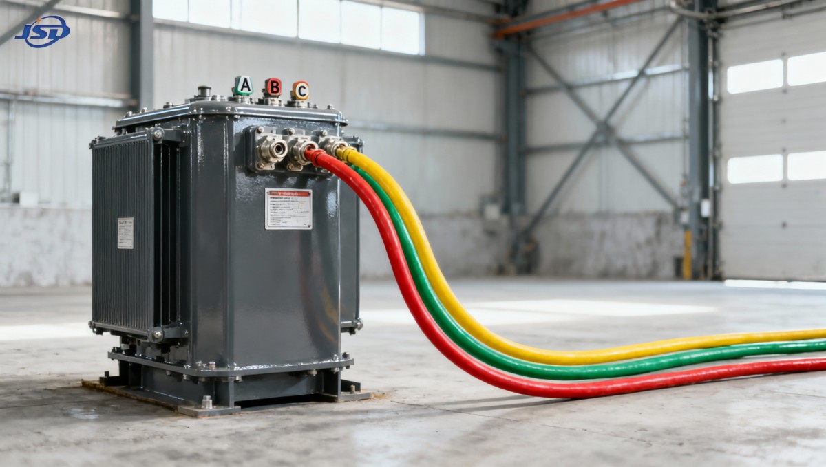
For example, the 33kV Oil-Immersed Power Distribution Transformer is engineered precisely for such environments. Its 33 kV/0.4 kV ratio, IP65-rated enclosure, and FR3 vegetable oil insulation support stable operation in demanding settings — from petrochemical facilities to wind farm interconnection points. With off-circuit tap changing and verified overload capacity up to 150% for short durations (under oil temperature monitoring), it handles real-world variability without compromising voltage regulation or thermal safety.
Importantly, its design assumes — and accommodates — the natural imbalances of modern loads. That’s not an add-on feature. It’s built into the magnetic circuit, winding arrangement, and cooling strategy.
Practical Steps Before You Connect Anything
If you’re evaluating a transformer for a three-phase application, skip the “can it power something?” question. Ask instead:
- What’s the worst-case load imbalance? Measure or estimate the maximum kVA difference between any two phases — not just total load.
- Is neutral continuity maintained end-to-end? Trace the neutral path from source transformer to final load. Is it sized for zero-sequence current? Is it bonded correctly?
- What protection scheme is in place? Does it include voltage unbalance detection (e.g., ANSI 47), neutral current monitoring, and thermal overload logic — not just overcurrent?
- Does the transformer’s nameplate specify three-phase operation? If it says “single phase” — even if rated for the same voltage and kVA — it’s not suitable for direct three-phase service without neutral.
When in doubt, measure — not assume. Use a power quality analyzer to capture voltage, current, harmonics, and neutral shift over a full operational cycle. The data rarely lies. And if your readings show >3% voltage unbalance under normal load, the root cause is almost certainly upstream transformer selection — not downstream equipment faults.
At Jinshida Electric Power Technology Co., Ltd., our technical team regularly supports operators facing exactly this scenario — not with generic advice, but with site-specific verification: checking vector groups, validating neutral integrity, reviewing relay settings, and confirming thermal margins. Because reliability isn’t defined by startup success. It’s proven over years of stable, uneventful operation — under real load, real imbalance, and real environmental stress.
Using a single phase transformer to backfeed or supplement an unbalanced three-phase system without neutral isn’t a shortcut. It’s a deferred failure. The right solution starts with matching the transformer’s fundamental architecture to the system’s electrical behavior — not just its voltage rating.

Get a Quote
Regardless of whether you require general advice or specific support, we are happy to help you.
Send Us Your Inquiry Today

Jinshida Electric remains committed to contributing to global energy development through professional manufacturing and superior service.