





What happens to a 3-phase transformer when one supply phase is lost?
A 3 phase transformer can remain energized when one incoming supply phase is lost, but its output may no longer be suitable for normal operation. Some loads lose power immediately; others keep running with unbalanced voltages and excessive current. Motors are particularly vulnerable because a running motor can continue turning while its windings overheat.
Treat a confirmed phase loss as an abnormal supply condition requiring prompt isolation through the approved shutdown procedure. A lit indicator, a voltage reading on every secondary terminal, or continued production does not establish that the supply is healthy. The transformer connection, neutral arrangement, magnetic core, and connected loads all influence what remains energized.
The location of the open circuit changes the result
“One phase lost” can describe several different faults: an upstream utility conductor opens, one primary fuse operates, a contactor pole fails, or a secondary cable connection breaks. These faults do not produce identical measurements. A downstream open conductor can leave the transformer operating normally while exposing one feeder to single-phasing. An open primary conductor changes the excitation of the transformer itself.
Record where the abnormal condition was detected and which protective device operated. If the primary supply is healthy but one outgoing feeder has no current in one conductor, investigate that feeder and its switching equipment. If the abnormality appears across several secondary feeders simultaneously, the transformer supply or a common connection becomes a stronger suspect.
A loose, high-resistance connection also deserves attention. It can show nearly normal voltage with little load, then develop a severe voltage drop and localized heating as demand increases. The difference between a complete interruption and a deteriorating connection affects both diagnosis and repair.
Winding connections determine which voltages survive
The nameplate vector group and the actual neutral connections are essential to interpreting the fault. The following comparisons describe broad behavior; they are not substitutes for the transformer’s connection diagram or a system-specific assessment.
A delta secondary adds another interaction because its closed winding path permits internal circulating currents under certain unbalanced conditions. A star secondary supplies a neutral reference when that neutral is connected, but this does not restore missing primary excitation. Primary and secondary connections must therefore be considered together.
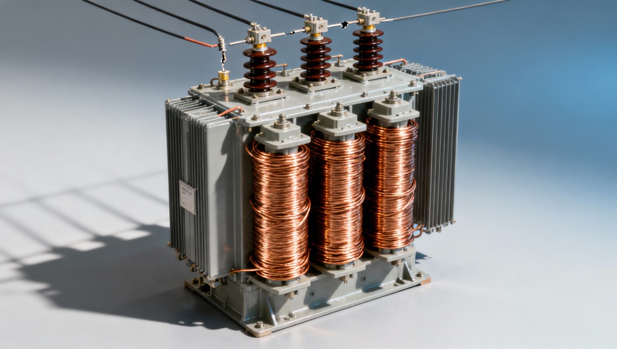
Core construction matters as well. A three-limb core magnetically couples the phases differently from a bank of separate single-phase transformers. Flux from energized limbs can induce voltage in a winding whose incoming conductor is open. Consequently, a terminal associated with the missing supply phase can still present hazardous voltage.
An open supply line is not a designed open-delta bank
A deliberately engineered open-delta bank uses two transformers with specified connections and loading limits. Losing one incoming line to an ordinary three-phase transformer does not automatically create that arrangement. Applying an open-delta capacity rule to this fault can lead to an unsafe loading decision.
There is no universal percentage of rated capacity available after a supply phase disappears. Any exceptional continued operation requires engineering confirmation of the winding arrangement, current distribution, voltage quality, protection, and thermal limits.
Why connected equipment can fail before the transformer trips
The immediate danger often appears in the load. A running induction motor subjected to single-phasing can continue rotating, particularly with a light mechanical load. Its remaining supply currents increase, torque capability falls, and heating becomes uneven. A motor that stops may then fail to restart while drawing damaging current.
Voltage unbalance also creates a negative-sequence component: an electrical field rotating opposite to the normal field. This produces additional rotor heating. Even when the motor appears to run smoothly, its thermal condition can deteriorate faster than the transformer’s temperature indication suggests.
Electronic loads behave differently. Drives and rectifiers may trip on input phase loss, undervoltage, or excessive DC-bus ripple. Others continue operating temporarily with increased stress on their input components. Single-phase loads connected to different secondary phases can show a mixed pattern of normal operation, dimming, resets, or loss of power.
The transformer is not automatically protected by reduced total output. Current becomes unevenly distributed, so individual windings or connections can overheat even while aggregate loading appears moderate. Remaining line currents are determined by the load response: equipment attempting to maintain power behaves differently from a resistive load whose power falls as voltage drops.
An ordinary overcurrent device may not operate promptly because it responds to current magnitude and its time characteristic. A harmful unbalance can persist without crossing its trip threshold. Transformer temperature protection also has thermal delay and does not directly represent the temperature of every connected motor.
Voltage readings that can give false reassurance
Measurable voltage on all three phases does not prove that all three supply paths are intact. Magnetic coupling, connected rotating machines, capacitive coupling, and alternative sources can produce voltage on an apparently disconnected phase. A lightly loaded measurement can therefore look much healthier than the circuit behaves under demand.
Useful diagnosis compares all three line-to-line voltages at the same location and operating condition. On a four-wire system, the three line-to-neutral readings provide additional information. Measurements taken at different times while loads are changing can create a misleading picture of balance.
Current measurements add evidence that voltage alone cannot supply. Zero current in one incoming conductor, combined with current in the other two, strongly suggests an interrupted path when three-phase load is expected. However, current measured downstream can be affected by connected motors or local generation, so the measurement location must be recorded.
For an initial voltage-unbalance assessment, calculate the average of the three line-to-line voltage magnitudes, find the largest absolute departure from that average, and divide that departure by the average. Multiply by 100 to express the result as a percentage. This magnitude-based calculation is useful for screening; it is not the same as a negative-sequence measurement and does not establish an acceptable operating limit.
Compare results with the connected equipment’s stated limits and the configured protection settings. A transformer’s rated voltage alone cannot determine whether a motor, drive, or control system can tolerate the measured condition.
Separate phase loss from a broken neutral
An open neutral can resemble phase loss because lights change brightness and single-phase equipment behaves erratically. On an unbalanced star-connected load, losing the neutral allows the load star point to move. Some line-to-neutral voltages rise while others fall, even though the three line-to-line supply voltages remain relatively normal.
That pattern differs from an interrupted phase conductor. Replacing a suspected phase fuse without investigating the neutral can leave the actual fault unresolved. It is especially important to distinguish these conditions where sensitive single-phase equipment shares a three-phase, four-wire supply.
Earth measurements need careful interpretation too. Protective earth is not a substitute for the neutral, and an unexpected phase-to-earth reading cannot independently identify the failed conductor. Grounding arrangement, measurement reference, and possible backfeed all affect the result.
Isolation, fault finding, and restoration
When phase loss is confirmed, stop affected equipment and isolate the circuit using the site’s established electrical procedure. Avoid repeated restart attempts or repeated fuse replacement: a fuse can be the consequence of a winding fault, cable defect, or downstream short circuit. Its operation identifies an interrupted path, not necessarily the original cause.
The investigation should proceed in a controlled sequence:
- Preserve available evidence. Record alarms, relay events, operating load, unusual sound, and the positions of protective devices before resets erase useful information.
- Establish isolation from every source, including generators, photovoltaic inverters, energy storage, and possible secondary backfeed. Apply lockout and verify absence of voltage with suitable equipment under the approved procedure.
- Inspect the interrupted path for damaged fuse holders, overheated joints, failed contactor poles, cable damage, and winding-related indications. Electrical testing should follow the equipment condition and manufacturer’s instructions.
- After repair, confirm supply voltage, phase sequence where relevant, neutral continuity, and protection readiness before staged re-energization. Observe phase currents and voltages as loads return.
Live measurements, where necessary for diagnosis, require qualified electrical personnel and an appropriate work procedure. Opening a secondary breaker alone does not isolate the primary, and an open primary conductor does not establish that the corresponding terminal is dead.
Energy storage changes the isolation boundary
A site incorporating a 125kW/261kWh Commercial & Industrial Energy Storage System has an additional power source to include in the investigation. Its specified 380 V / 400 V AC interface must be considered alongside the transformer and distribution arrangement. Battery capacity and rated power do not establish whether the installation can support loads during a missing utility phase.
Continued supply requires a suitable islanding arrangement, transfer equipment, protection coordination, and compatible inverter operating capability. Confirm these features from the actual design and commissioned settings. A grid-connected storage cabinet must not be assumed to reconstruct a missing phase or keep the affected bus safely energized.
Protection must recognize the abnormal supply
Phase-loss or phase-unbalance protection can initiate shutdown before prolonged operation damages connected equipment. Its effectiveness depends on where it measures and how it trips the circuit. A relay upstream of a failing contactor cannot directly detect an open pole downstream; a relay monitoring only voltage can also face misleading regenerated voltage from rotating loads.
Protection selection should therefore address the actual fault paths, including voltage and current unbalance where appropriate. Trip delays must coordinate with normal switching events while remaining compatible with the thermal limits of connected equipment. Settings copied from a different installation do not establish that coordination.
After restoration, confirm stable operation under representative load rather than relying solely on an unloaded voltage reading. Persistent current imbalance, abnormal heating, or recurring phase-loss alarms warrants further investigation before unrestricted service resumes.

Get a Quote
Regardless of whether you require general advice or specific support, we are happy to help you.
Send Us Your Inquiry Today

Jinshida Electric remains committed to contributing to global energy development through professional manufacturing and superior service.