





Choosing a three-phase distribution transformer for a grounded neutral
Choosing a three-phase distribution transformer for a grounded neutral
Choosing a three phase distribution transformer for a grounded-neutral system requires more than matching voltage and kVA ratings. The winding connection, accessible neutral terminal, grounding arrangement, and zero-sequence characteristics all affect whether earth-fault protection will operate as intended. Load imbalance and harmonics can also change the thermal duty significantly, even when total demand appears comfortably below the nameplate rating.
The useful starting question is not simply, “Does this transformer have a neutral?” It is, “What current must that neutral carry, and where will fault current return?” Answer those questions before comparing prices or accepting a standard winding configuration.
Define which neutral needs grounding
A grounded medium-voltage supply does not automatically provide a usable grounded neutral on the low-voltage side. In an ordinary two-winding transformer, the windings are electrically isolated. The secondary grounding arrangement must therefore be designed in its own right, while remaining coordinated with upstream protection and utility requirements.
For a commercial building supplied at 20 kV and distributed at 400/230 V, the usual requirement is a low-voltage star winding with its star point brought out to a neutral terminal. That terminal serves both the intended grounding connection and the load-neutral connection, subject to the installation design. A delta secondary does not provide the same directly accessible star-point neutral.
Also distinguish neutral grounding from equipment earthing. Bonding the transformer enclosure to the protective earthing system does not establish the secondary neutral reference. The single-line diagram should show both arrangements clearly, including any grounding impedance and the intended neutral-to-earth bonding location.
Read the vector group, then check what it does not tell you
A delta-primary, star-secondary connection with an accessible neutral is a common candidate for low-voltage four-wire distribution. Under IEC notation, Dyn11 is one familiar example: the lowercase “n” indicates that the low-voltage neutral is brought out, while the clock number identifies phase displacement. It is an option to evaluate, not a universal specification.
The delta winding provides an internal circulating path associated with secondary zero-sequence currents. These currents are not transferred into the primary line conductors as zero-sequence line current. This distinction matters when locating earth-fault protection: an upstream residual-current measurement should not be assumed to detect a downstream earth fault across that delta winding.
Grounded star-star designs require closer examination of the complete arrangement. Core construction, primary neutral grounding, and any delta tertiary affect zero-sequence behavior. Two transformers with identical kVA and voltage ratings may therefore produce different earth-fault responses. Ask for the proposed winding diagram and zero-sequence information rather than relying on “suitable for grounded systems” in a quotation.
For parallel operation, phase displacement is only one acceptance condition. Ratio, tap position, impedance, phase sequence, and neutral arrangements must also be compatible. A replacement transformer can match the operating voltage yet still be unsuitable for connection to the existing bus.
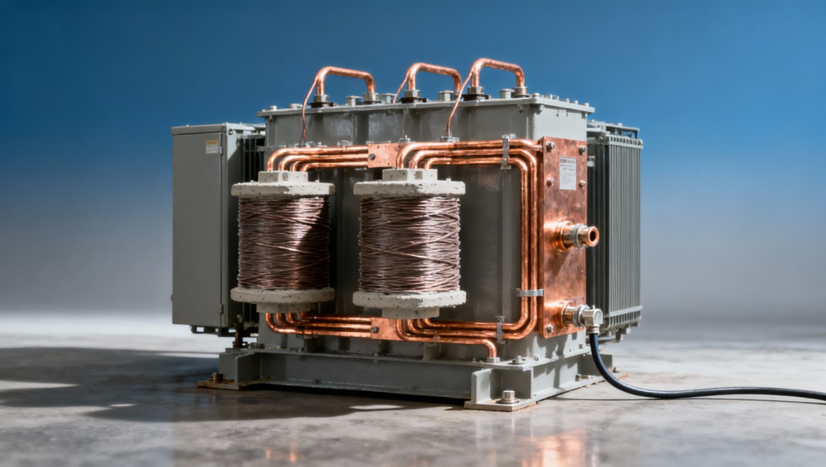
Make the grounding method part of the protection study
Solid grounding, resistance grounding, and other grounding methods impose different duties. A solidly grounded secondary can support substantial earth-fault current, but the actual value depends on transformer sequence impedances and the complete fault-loop impedance. A low-resistance metallic return path and an electrode-dependent return path should not be treated as equivalent.
Resistance grounding intentionally limits current. Whether it is appropriate depends on voltage, connected loads, continuity requirements, and applicable rules. It should not be substituted casually into a conventional four-wire installation serving line-to-neutral loads. The grounding resistor, monitoring scheme, insulation requirements, and fault-clearing philosophy need to be designed together.
For a single-line-to-ground fault, the calculation uses positive-, negative-, and zero-sequence networks, together with grounding and fault impedances. The nameplate percentage impedance normally used for three-phase short-circuit calculations is not enough by itself. Request zero-sequence impedance data appropriate to the proposed winding connection and grounding condition, or agree on an engineering assessment where measured data are unavailable.
Protection must work at both extremes. Maximum prospective fault current determines interrupting and withstand duties; minimum fault current determines whether a distant fault will clear promptly. Check sensor placement too. A residual current transformer must encompass the intended live conductors, including the neutral where applicable, while excluding the protective earth conductor.
Size for phase duty and neutral heating—not aggregate kVA alone
Consider a facility with three-phase motors, single-phase office circuits, and electronic power supplies. Its total demand may look balanced on a monthly report while one phase is heavily loaded during a particular shift. Evaluating only aggregate kVA can hide a winding overload. Review maximum phase current and realistic operating combinations, not just the sum of connected loads.
Nonlinear loads add another issue. Triplen harmonic components from single-phase loads can add in the neutral rather than cancel. Some modern equipment has effective harmonic mitigation, so neither “all electronic loads are severe” nor “balanced loads mean no neutral current” is a safe assumption. Use equipment data or a measured harmonic spectrum where available.
Ask the manufacturer to state the continuous current rating of the neutral terminal and its internal connections. A large external neutral cable cannot compensate for an inadequately rated internal connection. Where harmonic loading is significant, assess additional winding losses, temperature rise, and any required derating or harmonic-duty design. A larger standard kVA rating is not automatically the best remedy.
As a useful scale check, a 1,000 kVA transformer at 400 V has a rated three-phase line current of approximately 1,443 A, using I = S / (√3 × V). That establishes the nominal phase-current basis—not the acceptable neutral current or harmonic loading capability.
Evaluate the physical installation alongside the electrical design
Cast-resin dry-type equipment is worth considering for indoor industrial and commercial installations where liquid containment and fire strategy influence equipment selection. It still needs adequate ventilation, suitable clearances, and an enclosure matched to dust, moisture, and access conditions. Cast resin does not make every installation environment acceptable.
For a 20 kV project, Jinshida Electric Power Technology Co., Ltd. offers a 20kV Three-Phase Cast Resin Dry-Type Distribution Transformer range with stated 0.4 kV or 0.415 kV secondary options and a high-voltage tapping range of ±2 × 2.5%. Its manufacturing and application-engineering scope makes the supplier discussion relevant beyond nominal ratings: request confirmation of the winding connection, neutral rating, and grounding compatibility for the particular unit being offered.
The published IP23 enclosure and F1 fire-behavior classification address different concerns. Neither establishes suitability for every outdoor, contaminated, or fire-sensitive location. Confirm the applicable classification evidence and actual enclosure configuration. Likewise, the stated capability of 120% rated load with forced-air cooling should be treated as conditional: ask about permissible duration, ambient temperature, temperature-rise limits, and operation following fan failure.
Dry-type transformers also require inspection. Ventilation passages can become obstructed, terminals need appropriate checks, and temperature protection must remain functional. Access for these tasks belongs in the layout review, especially when the neutral connection or grounding conductor sits behind a crowded cable termination area.
Turn supplier claims into an auditable selection
A long list of standards or certification marks is less useful than documents tied to the offered design. IEC 60076-11 is relevant to dry-type transformers, with other IEC 60076 provisions applying as appropriate. Projects using IEEE requirements need the corresponding contractual specification. An ISO 9001 quality-management certificate is not evidence that a particular transformer satisfies every electrical requirement.
Before technical approval, close these specific gaps:
- Obtain the guaranteed vector group, terminal diagram, neutral current rating, and neutral insulation details.
- Confirm impedance values, tolerances, and the zero-sequence data or assumptions used in the protection study.
- Request losses and temperature-rise guarantees for the selected rating, stated reference conditions, and cooling mode.
- Identify routine tests, any required type or special tests, and which reports apply to the offered design.
- Agree on temperature alarms, trip contacts, fan controls, and interfaces with site protection.
Compare efficiency claims only at stated loading, power factor, and temperature conditions. A headline figure above 99% does not establish annual energy performance. Guaranteed no-load and load losses, combined with the expected duty profile, provide a more useful comparison.
The final approval package should connect three documents: the transformer data sheet, the grounding diagram, and the protection study. If they disagree about the neutral connection, available fault current, or clearing method, selection is not complete. Resolve that mismatch before releasing the transformer for manufacture—not after it reaches the switchroom.

Get a Quote
Regardless of whether you require general advice or specific support, we are happy to help you.
Send Us Your Inquiry Today

Jinshida Electric remains committed to contributing to global energy development through professional manufacturing and superior service.