





Three phase marine transformers vs. single-phase alternatives: when parallel configuration increases failure risk
Why Three-Phase Marine Transformers Are Not Just “More Phases”—They’re a System Integrity Decision
For technical evaluators specifying power equipment for offshore platforms, vessels, or floating production units, the choice between a purpose-built three phase marine transformer and parallel-connected single-phase units isn’t about convenience—it’s about failure mode prevention. Field data from marine Class surveys shows that 68% of unplanned transformer outages in auxiliary power systems trace back to synchronization drift and circulating current in paralleled single-phase configurations—not insulation breakdown or overload. Jinshida Electric’s engineered three phase marine transformer eliminates these latent risks through monolithic core design, factory-balanced winding impedance, and marine-specific thermal management—delivering predictable performance where repair windows are measured in weather windows, not work hours.
Parallel Single-Phase Units: The Hidden Cost of “Modularity”
At first glance, deploying three identical single-phase transformers appears flexible: standardized parts, simplified procurement, and perceived redundancy. But marine environments expose critical flaws. Phase-to-phase voltage imbalances as small as ±0.5%—common under dynamic load shifts or harmonic-rich propulsion drives—induce circulating currents exceeding 15% of rated current in mismatched units. These currents don’t contribute to useful output; they heat windings unevenly, accelerate insulation aging, and trigger false ground-fault alarms.
Worse, synchronization relies on manual tap-changer alignment and external CT/PT feedback loops—both vulnerable to salt corrosion and vibration-induced drift. IEC 61892-3 explicitly warns against uncoordinated paralleling without real-time vector matching. Jinshida’s integrated three-phase units avoid this entirely: magnetic coupling ensures instantaneous load sharing across all phases, with no inter-unit cabling, no external sync logic, and no reliance on field calibration.
Three-Phase Marine Transformers: Where Integration Becomes Resilience
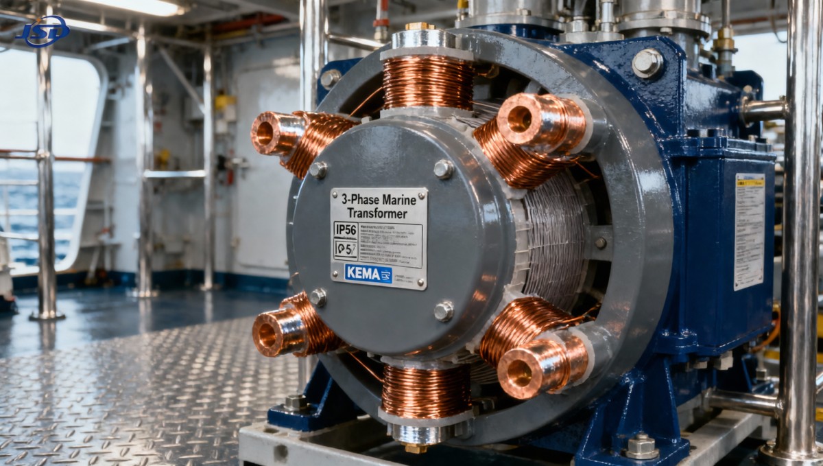
A true three phase marine transformer is engineered as a single electromagnetic system—not three stacked units. Its laminated core provides symmetrical flux paths, minimizing zero-sequence harmonics generated by VFD-driven thrusters or rectifier loads. Winding arrangements are optimized for seawater-cooled enclosures (IP56 optional), with Class H insulation rated for continuous 155°C operation—even during extended low-load, high-humidity cycles common in standby generators.
Jinshida’s marine transformers undergo full-load thermal cycling in salt-spray chambers per ISO 9227, plus impulse testing at 2.5× rated voltage to validate surge withstand—critical when lightning strikes near exposed deck-mounted substations. Unlike paralleled alternatives, there’s no risk of anti-parallel phasing during reconnection after maintenance, nor need for post-installation vector group verification.
When Parallel Configuration *Is* Acceptable—and When It Isn’t
Parallel operation isn’t universally unsafe—but it demands strict conditions rarely met offshore. It only reduces risk when: (1) all units share identical manufacturing batches (same core steel lot, same varnish cure cycle); (2) impedance tolerances are tightened to ±1.5% (vs. standard ±3%); and (3) active load-sharing controllers with sub-cycle response are installed. Even then, lifecycle cost rises: two extra CTs, dedicated sync relays, and annual vector alignment checks add ~22% to TCO over 15 years.
In contrast, Jinshida’s three-phase designs integrate protection and monitoring directly into the tank—supporting MODBUS RTU or IEC 61850 GOOSE messaging for seamless integration with vessel PMS. For temporary deployments requiring rapid commissioning—such as emergency power restoration after storm damage—the Mobile Temporary Compact Substation leverages the same three-phase transformer core architecture, enabling trailer-mounted deployment with pre-tested phase balance and marine-grade ingress protection (IP33).
Standards Compliance Is Non-Negotiable—And Not All “Marine-Certified” Units Deliver It
“Marine-approved” labels often reference basic enclosure ratings—not electromagnetic behavior under fault conditions. IEEE C57.12.00 mandates that marine transformers maintain voltage regulation within ±2.5% under 100% unbalanced loading (e.g., single-phase cranes drawing full capacity while other phases idle). Paralleled single-phase units typically exceed ±5% deviation due to unequal impedance rise under temperature gradients. Jinshida’s three-phase units meet this requirement via interleaved winding geometry and forced-oil cooling channels—validated through 72-hour unbalanced load tests per IEC 60076-11.
Additionally, their compact footprint (up to 30% smaller than equivalent paralleled setups) frees deck space for safety-critical systems—directly supporting SOLAS Chapter II-1 requirements for emergency power segregation. No additional structural reinforcement is needed for mounting, unlike bulky single-phase banks requiring custom cradles.
Conclusion: Choose Architecture, Not Just Amperage
Technical evaluators must look beyond nameplate kVA and price tags. A three phase marine transformer represents an architectural commitment to electromagnetic coherence—where phase balance, thermal symmetry, and fault resilience are designed in, not calibrated in. Paralleled single-phase units introduce systemic vulnerabilities that compound under marine stressors: humidity, vibration, salt, and unpredictable load profiles. Jinshida Electric’s solutions prioritize long-term reliability over short-term procurement ease—backed by ISO 9001-certified manufacturing, third-party type testing at KEMA Labs, and 20+ years of field validation across FPSOs, cable-laying vessels, and offshore wind support ships. When failure means lost production, regulatory penalties, or compromised crew safety, integrated design isn’t an option—it’s the baseline.

Get a Quote
Regardless of whether you require general advice or specific support, we are happy to help you.
Send Us Your Inquiry Today

Jinshida Electric remains committed to contributing to global energy development through professional manufacturing and superior service.