





Three-Phase ONAN Transformer Vector Groups: Matching System Requirements
The correct vector group for a three phase ONAN transformer is the one that fits the network’s grounding arrangement, required phase displacement, and operating connections. Dyn11 can provide a low-voltage neutral and a delta path for zero-sequence balancing currents, while Yyn0 gives zero displacement but requires closer examination of neutral grounding and zero-sequence impedance. Neither designation is universally better.
ONAN means oil natural, air natural: it describes how heat moves through the transformer oil and into the surrounding air. It does not determine the winding connection, neutral availability, or phase relationship. Those electrical characteristics must be specified independently, particularly where transformers supply four-wire loads, connect renewable generation, or operate in parallel.
Read the vector group as an electrical relationship
Under IEC notation, capital letters identify the higher-voltage winding connection and lowercase letters identify the lower-voltage winding connection. D or d means delta, Y or y means star, and Z or z means zigzag. N or n indicates that the corresponding neutral point is brought out to a terminal. The winding order follows voltage rating, not the direction of power flow.
The clock number expresses the lower-voltage phasor position relative to the higher-voltage reference, with each hour representing 30 electrical degrees. For Dyn11, the higher-voltage winding is delta-connected, the lower-voltage winding is star-connected with an accessible neutral, and the lower-voltage phasor occupies the 11 o’clock position. Under this convention, it leads the higher-voltage reference by 30 degrees. Dyn1 represents a 30-degree lag; Yyn0 has zero displacement.
These relationships must be interpreted using the specified terminal markings and phase sequence. A shorthand statement such as “30-degree shift” is insufficient for interconnection work because it omits the direction. Drawings, relay settings, and commissioning records should all use the same reference convention.
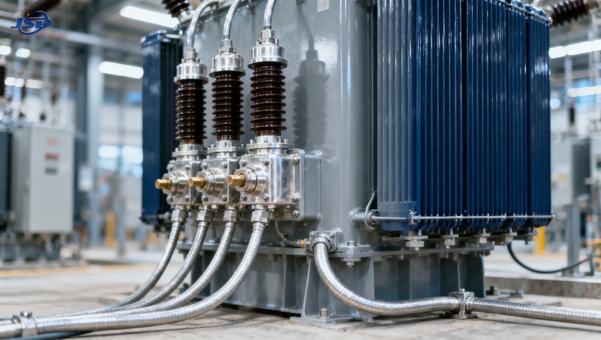
The designation identifies the connection, but it does not fully describe performance. Two transformers with the same vector group can have different zero-sequence impedances, neutral ratings, short-circuit impedances, and thermal capabilities.
Neutral availability is not the same as an effective grounding design
A star-connected winding with an accessible neutral makes a three-phase, four-wire supply possible. It does not, by itself, establish whether that neutral should be solidly grounded, resistance grounded, or connected through another grounding arrangement. The choice controls earth-fault current, temporary overvoltages, touch-voltage considerations, and the sensitivity required from protection.
For a Dyn transformer supplying grounded low-voltage loads, zero-sequence current can flow in the star-connected winding and produce balancing circulating current inside the delta. Corresponding zero-sequence line current does not pass into the three-wire higher-voltage circuit. This distinction matters: the delta provides an internal path, but it is not an external neutral conductor and does not eliminate the need to design the lower-voltage grounding system.
The upstream network still supplies energy during a downstream earth fault. Blocking zero-sequence line-current transfer is not equivalent to isolating the upstream system from every fault component. Positive- and negative-sequence currents, fault magnitude, and transformer impedance remain relevant to coordination.
For Yyn0, the lowercase n confirms only that the lower-voltage neutral is accessible. It says nothing about an accessible higher-voltage neutral. If the higher-voltage star point is isolated, the source cannot provide the same zero-sequence current path as a grounded star connection. With no delta stabilizing winding, zero-sequence excitation and voltage distortion depend strongly on the magnetic construction and operating conditions.
A three-limb core, a five-limb core, and a bank of single-phase units do not offer identical zero-sequence flux paths. In a three-limb design, zero-sequence flux can return through oil, structural parts, and the tank, affecting impedance and stray heating. Consequently, Yyn0 should not be rejected categorically, but it should not be selected solely because zero phase displacement appears convenient.
Where earth-fault calculations depend on transformer behavior, request zero-sequence impedance data for the intended terminal and grounding configuration. Positive-sequence percentage impedance alone is not an adequate substitute.
Unbalanced loads and harmonics expose connection limitations
A four-wire industrial or commercial network may have uneven single-phase loading even when its total demand remains below the transformer’s kVA rating. The resulting neutral current and phase-voltage imbalance require separate assessment. An accessible neutral does not prove that the winding, neutral lead, bushing, and termination can carry the required continuous current.
Zigzag connections can provide a useful path for zero-sequence currents and support phase-to-neutral voltage performance under unbalanced loading. Their suitability still depends on winding design and rated duty. A zigzag grounding transformer, for example, may be designed primarily for short-duration earth-fault current rather than continuous load supply; its function should not be confused with that of a full-rated distribution transformer.
Delta windings also provide a circulating path for triplen components, including third-harmonic components associated with magnetizing behavior. This helps control certain voltage-distortion effects, but it does not make a Dyn transformer a general-purpose harmonic filter.
On a balanced four-wire system, triplen harmonic currents from single-phase nonlinear loads are in phase and add in the neutral rather than cancelling. The delta winding does not remove that current from the lower-voltage neutral. Nor does it eliminate heating from other harmonic orders, such as the fifth and seventh.
Where nonlinear loading is material, the specification should include the expected harmonic spectrum, neutral-current duty, and thermal assessment. ONAN cooling describes the cooling mechanism, not permission to carry arbitrary harmonic loading at nameplate kVA. Any loading allowance or derating must account for winding losses, stray losses, ambient conditions, and the manufacturer’s design limits.
Parallel operation requires more than matching “Dyn”
Two transformers feeding the same bus must present compatible secondary voltage phasors before their bus connection is closed. Dyn11 and Dyn1 differ by 60 electrical degrees when connected using corresponding phase labels. Closing them onto the same bus in that condition creates a severe mismatch, not a manageable load-sharing error.
Some vector-group differences can be accommodated through engineered changes to external phase connections. That possibility is not permission to improvise terminal swaps. The completed arrangement must preserve the intended bus phase sequence, grounding behavior, protection references, and insulation requirements, and it must be confirmed by phasing tests.
Even matching vector groups do not establish satisfactory parallel operation. The evaluation must also address:
- Voltage ratio and tap position: unequal no-load secondary voltages drive circulating current before useful load is supplied.
- Short-circuit impedance: unequal per-unit impedances cause unequal loading relative to each transformer’s rating.
- Impedance angle: different resistance-to-reactance relationships affect active and reactive load sharing.
- Phase sequence and terminal identification: matching nameplates cannot correct incorrectly connected cables.
- Neutral and earthing connections: parallel neutral paths can alter zero-sequence current sharing and earth-fault protection behavior.
For approximately equal ratios and similar impedance angles, load shares inversely with impedance in ohms referred to the common side. Rating therefore matters when comparing percentage impedances: identical percentage values on differently rated transformers do not mean identical ohmic impedance. The proposed combination should be checked at maximum demand, minimum demand, and relevant tap positions.
Protection must reflect the connection actually installed
Transformer differential protection compares currents from windings with different voltage and current relationships. For a delta–star transformer, the relay must compensate for phase displacement, ratio, and applicable zero-sequence effects. Numerical relays can perform this internally, but their settings must match the installed winding connections and current-transformer arrangements.
Incorrect compensation can produce differential current during healthy load or external faults. The error can remain hidden at low load and become significant during a through-fault. Nameplate verification, current-transformer polarity checks, and relay testing should therefore be treated as connected tasks rather than separate paperwork exercises.
Restricted earth-fault protection requires a suitable neutral arrangement and correctly positioned current transformers around the protected zone. Its implementation cannot be inferred from the vector group alone. Neutral grounding impedance, conductor routing, and any parallel earth-return paths influence the measurement.
Renewable-generation connections add another constraint: the utility may require a particular grounding interface or phase relationship. Converter controls do not replace transformer zero-sequence analysis. The collector-system earth-fault study must include winding connections, grounding devices, cables, and the operating configuration, including outages that remove a grounding source.
Standby-source integration raises a related issue. A three-phase, four-wire Silent Canopy Diesel Generator Set connected through an automatic transfer arrangement makes neutral switching and neutral-to-earth bonding part of the same system assessment. Its four-wire output does not determine the transformer vector group. Whether the transfer switch switches the neutral, and which source establishes the active grounding reference, can change earth-fault paths. Closed-transition operation also requires synchronization checks; a matching nominal voltage is insufficient.
Specify standards and evidence, not just a nameplate code
IEC 60076-1 provides the general framework for power-transformer ratings, connection symbols, and relevant tests. IEC 60076-8 provides application guidance, including connection behavior and parallel operation. For mineral-oil-immersed units, IEC 60076-7 addresses loading considerations. The contract should identify the applicable editions and any utility requirements rather than assuming that a general statement of IEC compliance resolves every application detail.
The transformer schedule should state the vector group alongside rated voltages, tap range, frequency, short-circuit impedance and its tolerance, neutral-terminal requirements, grounding arrangement, and load characteristics. Where relevant, it should also request zero-sequence impedance, neutral-current capability, and details of any stabilizing winding.
Connection-symbol and phase-displacement verification belong in factory acceptance documentation. Zero-sequence measurements may require an explicit agreement on test configuration and reporting. Site commissioning must then confirm actual phase sequence and phasing, since factory results cannot verify the external cables or switchgear connections.
A technically complete selection is therefore more specific than “ONAN, Dyn11.” It establishes which neutral is available, how it is grounded, how earth-fault current returns, which phase relationship exists at each bus, and whether the transformer can share load with existing equipment. Where these conditions are defined and supported by calculations and test records, the vector group becomes a verified system interface rather than an isolated nameplate choice.

Get a Quote
Regardless of whether you require general advice or specific support, we are happy to help you.
Send Us Your Inquiry Today

Jinshida Electric remains committed to contributing to global energy development through professional manufacturing and superior service.