





Substation oil immersed power transformers: how dissolved gas analysis (DGA) patterns differ between OLTC and non-OLTC units
For substation oil immersed power transformer maintenance professionals, understanding how dissolved gas analysis (DGA) patterns differ between on-load tap changer (OLTC) and non-OLTC units is critical for accurate fault diagnosis and proactive asset management. This article decodes key DGA signature variations—such as elevated acetylene in OLTC-related arcing versus sustained methane/ethylene in thermal faults of non-OLTC units—helping field engineers distinguish operational anomalies from incipient failures.
Core DGA Gas Generation Mechanisms: OLTC vs. Main Tank
The fundamental difference lies not in the oil itself, but in localized energy input and physical environment. In non-OLTC transformers, fault gases originate almost exclusively from insulation degradation within the main tank—primarily cellulose paper and mineral oil under thermal or electrical stress. OLTC units, however, introduce a distinct secondary system: an isolated, oil-filled compartment housing mechanical contacts that interrupt load current during voltage regulation. This compartment operates under repeated switching arcs, transient overvoltages, and contact wear—processes that generate gases at rates and ratios fundamentally different from those in the main tank.
Acetylene (C₂H₂) is the most telling indicator. While any C₂H₂ above 1–2 ppm warrants investigation, its presence in OLTC oil—even without corresponding high hydrogen or methane—is strongly associated with intermittent arcing across tap selector or diverter switch contacts. In contrast, acetylene in main-tank oil typically signals severe internal faults: winding turn-to-turn short circuits, bushing flashovers, or core ground faults. Crucially, OLTC-related acetylene often appears *without* proportional increases in hydrogen (H₂), because arc energy is highly localized and oil circulation between compartments is intentionally restricted.
Gas Ratio Interpretation Requires Compartmental Awareness
Rogers’ ratios and Duval triangles are powerful tools—but they assume gas origin is homogeneous. Applying them to mixed-oil samples or ignoring compartment boundaries leads to misdiagnosis. For example:
- A ratio of C₂H₂/C₂H₄ > 3 in main-tank oil suggests high-energy discharge; the same ratio in OLTC oil may reflect normal switching activity during frequent tap changes under heavy load.
- Elevated CH₄ and C₂H₄ with low C₂H₂ in main-tank oil points to thermal faults (>300°C) in windings or magnetic circuits. The same pattern in OLTC oil, however, often indicates overheating of contact clamps or poor connection integrity—not arcing—and may correlate with increased contact resistance measured via dynamic resistance testing (DRT).
- H₂ concentration alone is unreliable: OLTC compartments frequently show H₂ levels 2–5× higher than the main tank due to partial discharges during contact transition, even when no incipient failure exists.
Therefore, diagnostic confidence requires *separate sampling*: dedicated OLTC oil samples drawn from the OLTC conservator or drain valve, and main-tank samples taken from the lower valve—never from a common sample port downstream of the interconnecting pipe.
Operational Context Modifies Gas Signatures
Gas generation rate is not static. It depends heavily on duty cycle and environmental conditions. An OLTC unit performing 200 tap changes per day in a mining operation—where voltage fluctuations demand frequent regulation—will accumulate acetylene faster than an identical unit in a stable transmission substation with weekly adjustments. Similarly, ambient temperature affects oil viscosity and bubble formation: colder oil slows gas release from solid insulation, delaying detection of early-stage thermal faults in non-OLTC units, while warm oil accelerates oxidation byproducts like CO and CO₂, masking subtle fault signatures.
Moisture content also plays a role. OLTC compartments are more prone to moisture ingress through breather seals or gasket aging. Water reacts with hot metal surfaces to produce hydrogen, inflating H₂ readings independently of electrical faults. In non-OLTC units, moisture primarily degrades paper insulation strength and accelerates aging—evidenced by rising CO/CO₂ ratios over time—not immediate gas spikes.
Practical Sampling Protocol
Standardized sampling mitigates false positives:
- Draw OLTC oil only after the unit has been de-energized for ≥4 hours to allow gases to equilibrate.
- Avoid sampling immediately after tap changes—the first 30 minutes post-operation shows transient C₂H₂ peaks unrelated to fault progression.
- Use nitrogen-purged syringes and triple-rinse technique to eliminate air contamination, especially critical for low-concentration H₂ and C₂H₂ measurements.
- Record ambient temperature, load history (kVA and duration), and last tap change time alongside each sample.
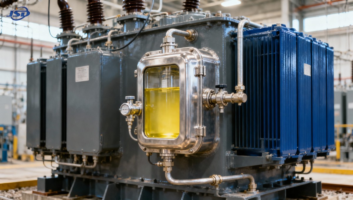
Material and Design Factors Influencing Gas Profiles
Transformer construction influences baseline gas levels. Units using high-permeability grain-oriented silicon steel sheets—like those in the Mining Flameproof Transformer—exhibit lower no-load losses and reduced core heating, resulting in lower background ethylene and methane generation under normal operation. This makes emerging thermal fault signatures easier to detect against a quieter baseline. Conversely, older units with aluminum windings may show elevated hydrogen from galvanic corrosion in moist oil, complicating interpretation of DGA trends unrelated to electrical faults.
Tank design matters too. Sealed OLTC compartments with limited oil volume concentrate gases faster than large main tanks, meaning ppm thresholds for action must be scaled accordingly. A 5 ppm C₂H₂ reading in a 10-liter OLTC reservoir carries greater significance than the same value in a 10,000-liter main tank.
When DGA Patterns Overlap: Resolving Ambiguity
Some scenarios defy simple compartment-based attribution. Oil migration through degraded gaskets or shared breathers can mix gases, producing hybrid signatures. In such cases, corroborative evidence is essential: infrared thermography of OLTC drive mechanisms, ultrasonic detection of partial discharge near tap selector housings, or chromatographic analysis of furanic compounds (2-FAL, 5-MF) to assess paper aging severity in the main tank. Furan analysis is particularly valuable when DGA shows moderate CH₄/C₂H₄ but no clear fault type—indicating slow thermal degradation rather than acute failure.
Finally, remember that DGA identifies *what* is happening chemically—not *why*. Elevated gases signal degradation processes, but root cause requires integration with electrical test data (turns ratio, winding resistance, SFRA), mechanical inspection records (contact wear, spring tension), and operational logs. A consistent rise in C₂H₂ in OLTC oil paired with increasing contact resistance and audible “crackling” during tap changes confirms arcing. Without those supporting data, the same gas trend could reflect temporary overload or transient overvoltage—not progressive failure.
DGA remains indispensable—but its diagnostic power emerges only when interpreted within the precise physical and operational context of each substation oil immersed power transformer’s architecture. Treating OLTC and non-OLTC units as functionally equivalent in gas analysis ignores the physics of their distinct failure modes and risks both premature intervention and dangerous oversight.

Get a Quote
Regardless of whether you require general advice or specific support, we are happy to help you.
Send Us Your Inquiry Today

Jinshida Electric remains committed to contributing to global energy development through professional manufacturing and superior service.