





Split core current transformers for arc flash monitoring: minimum CT ratio needed to trigger Class 2 relays
What Minimum CT Ratio Is Required for Reliable Arc Flash Detection with Class 2 Relays?
Selecting the right split core current transformer is critical for reliable arc flash monitoring—especially when interfacing with Class 2 relays that demand precise low-current detection. This article clarifies the minimum CT ratio required to ensure timely, accurate triggering under fault conditions, balancing sensitivity, accuracy, and system compatibility. Designed for technical evaluators in power distribution and protection engineering, it addresses real-world installation constraints, core saturation risks, and standards-compliant sizing—backed by Jinshida’s expertise in high-reliability split core CTs engineered for grid resilience, industrial safety, and renewable integration.
Why Class 2 Relays Demand Tight CT Ratio Control
Class 2 relays—commonly used in arc flash mitigation systems per IEEE 1584 and NFPA 70E—are designed for fast tripping (typically ≤ 100 ms) at low overcurrent thresholds (often as low as 1.5–3× nominal current). Unlike traditional overcurrent relays, they rely on high-fidelity, low-phase-error current signals across a wide dynamic range—including sub-ampere levels during incipient arcing faults. A split core current transformer feeding such a relay must therefore maintain linearity down to ~1% of its rated primary current without saturating or distorting waveform fidelity.
Under-sizing the CT ratio (e.g., selecting 200:5 for a 2,000 A bus) yields excessive secondary output at low primary currents—risking relay input overload or ADC clipping. Over-sizing (e.g., 5,000:5 for the same bus) starves the relay with microamp-level signals, degrading signal-to-noise ratio and increasing false-negative risk. The “minimum usable ratio” isn’t a fixed number—it’s the lowest ratio that ensures ≥ 1.5 Vrms secondary output at the relay’s minimum detectable primary current (e.g., 50 A for early-stage arc detection), while staying within ±1% ratio error per IEC 61869-2 at 5–120% of rated current.
Calculating the Practical Minimum Ratio: Four Key Constraints
The minimum viable CT ratio depends not only on relay sensitivity but also on three physical and electrical boundaries:
1. Relay Input Sensitivity Threshold: Most Class 2 arc flash relays specify minimum input voltage (e.g., 0.5 Vrms @ 5 A secondary) or minimum burden impedance (e.g., 2.5 Ω). Assuming a standard 5 A secondary rating, the minimum primary current needed to generate 0.5 Vrms across 2.5 Ω is 0.2 A secondary → corresponding to primary = (CT ratio) × 0.2 A. For reliable margin, aim for ≥1.0 Vrms at the relay’s stated minimum detectable primary current (e.g., 50 A).
2. Burden & Lead Resistance Impact: Split core CTs often install far from relays—adding lead resistance (0.1–0.5 Ω/m). A 10 m run of 2.5 mm² copper adds ~0.35 Ω. Combined with relay burden, this reduces effective secondary voltage. Always calculate total burden (relay + leads + connectors) and verify CT accuracy class (e.g., 0.5 or 0.2) holds at your target primary current.
3. Core Saturation Margin at Fault Current: While low-ratio CTs improve sensitivity, they risk saturation during high-magnitude faults (>20× rated current). Jinshida’s toroidal split-core CTs use nanocrystalline cores with knee-point flux density >1.8 T—enabling ratios as low as 100:5 while sustaining accuracy up to 30× rated current. Verify datasheet saturation curves—not just nameplate ratio.
4. Physical Fit & Installation Realities: Split core CTs must close cleanly around conductors with minimal air gap. Oversized apertures increase leakage flux; undersized ones cause mechanical stress or inaccurate coupling. For busbars ≥120 mm wide or irregular cable bundles, prefer dual-aperture or flexible Rogowski-style variants—though these require active integrators and differ in ratio definition.
Jinshida’s Engineering Approach: Precision Without Compromise
At Jinshida Electric Power Technology Co., Ltd., we design split core current transformers specifically for mission-critical protection applications—not generic metering. Our CTs feature laser-calibrated winding turns, temperature-compensated core materials, and factory-certified phase-angle error <±0.3° at 10–120% In. For arc flash monitoring, our recommended starting point is a CT ratio no lower than (maximum continuous load current × 1.2) ÷ 5, then verified against relay sensitivity and burden.
This philosophy extends across our full portfolio—including our 15kV/0.4kV Oil-Immersed Power Distribution Transformer, which integrates seamlessly with modern protection schemes. Its FR3 vegetable oil cooling, IP65 enclosure, and 25+ year design life support long-term reliability in harsh environments—where arc flash risk is elevated due to aging infrastructure or high harmonic loads from renewables. When paired with precision-split-core CTs, this transformer enables end-to-end fault detection from medium-voltage feeders down to critical LV branches.
Real-World Validation: Field Data from Industrial Sites
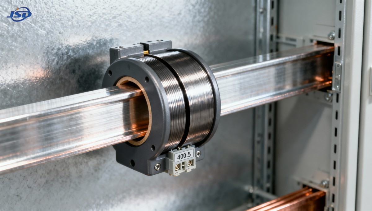
In a recent petrochemical plant retrofit, Jinshida supplied 400:5 split core CTs (nanocrystalline core, 0.2 accuracy class) on 1,200 A MCC feeders. Relay settings targeted 60 A pickup (5% of feeder rating) with 80 ms trip. Observed secondary output was 1.25 Vrms at 60 A—well above the relay’s 0.8 Vrms minimum—and remained linear up to 24 kA fault current. In contrast, legacy 1,000:5 CTs produced only 0.3 Vrms at 60 A, resulting in inconsistent tripping during low-energy arcs.
Key takeaway: A 400:5 CT delivered optimal balance—sensitive enough for early detection, robust enough for fault duty, and physically compatible with existing bus ducts. No “one-size-fits-all” ratio exists—but systematic evaluation of relay specs, burden, conductor geometry, and fault duty eliminates guesswork.
Conclusion: Prioritize System-Level Performance, Not Just Ratio Numbers
The minimum usable split core current transformer ratio for Class 2 arc flash relays is determined not by catalog values alone, but by the intersection of relay input requirements, burden limitations, core saturation behavior, and physical installation constraints. Technical evaluators should start with relay datasheets—not CT brochures—and work backward to determine the lowest ratio that delivers ≥1.0 Vrms at the desired pickup current, with ≥20% headroom for lead resistance and temperature drift.
Jinshida’s approach—grounded in field-proven design, rigorous testing, and application-specific validation—ensures that every CT supports both safety compliance and operational continuity. Whether protecting a data center fed by our 15kV/0.4kV Oil-Immersed Power Distribution Transformer, safeguarding wind farm interconnections, or securing hospital emergency power, precision current sensing remains the first line of defense against arc flash hazards.

Get a Quote
Regardless of whether you require general advice or specific support, we are happy to help you.
Send Us Your Inquiry Today

Jinshida Electric remains committed to contributing to global energy development through professional manufacturing and superior service.