





Specifying High-Capacity Substation Transformers for Peak Load Growth
Peak-load growth rarely arrives as a smooth, predictable curve. A substation may operate comfortably for years, then face a combination of feeder additions, industrial expansion, seasonal demand, distributed generation changes, or contingency transfers that pushes transformer loading closer to its limits. In that situation, specifying a high capacity substation transformer is not simply a matter of selecting the next larger MVA rating.
The sound decision is to define the required capacity from a documented load profile and operating duty, then verify that the selected unit can manage normal growth, credible contingencies, thermal aging limits, voltage regulation, fault-duty constraints, and future connection requirements. A transformer sized only for today’s peak may create an immediate bottleneck; one oversized without checking impedance, losses, transport limits, or minimum-load operation can introduce different technical and economic problems.
Start with the duty the transformer must actually carry
The nameplate MVA is a continuous rating under stated reference conditions. It is not, by itself, a forecast model or a guarantee that every future operating condition will be acceptable. Before comparing transformer offers, establish what the substation is expected to do in normal operation and during credible abnormal states.
Begin with interval load data where it is available. Annual maximum demand is useful, but it can conceal the duration and shape of loading. A short sharp peak, a sustained evening plateau, and a recurring summer overload can produce very different thermal conditions even when their maximum MW values are similar. Review active power, reactive power, power factor, seasonal ambient temperature, and expected load transfer arrangements.
A practical duty definition normally separates the following conditions:
- Base operation: expected loading after the transformer is commissioned, including the anticipated power factor.
- Planned growth condition: the forecast demand at the chosen planning horizon, with assumptions clearly identified.
- Contingency duty: loading after loss of a parallel transformer, feeder rearrangement, or another credible outage.
- Temporary overload duty: magnitude, duration, frequency, starting oil temperature, and required recovery period.
- Minimum-load condition: relevant where a large unit may remain lightly loaded for extended periods and no-load losses become significant.
MW alone does not define transformer capacity. The required MVA depends on power factor, and reactive power can rise as cable networks, motor loads, compensation equipment, or operating practices change. A forecast that assumes a constant power factor may understate the transformer duty. It is also important to distinguish coincident substation demand from the sum of connected loads. Connected capacity may be much higher than the load that occurs simultaneously, but diversity can decline as the network and customer mix change.
Use overload capability as a design input, not as hidden spare capacity
Loading guides permit controlled operation above a transformer’s continuous rating under defined thermal conditions. This can be useful during a planned maintenance outage or a short-duration emergency transfer. It should not be used to justify a transformer that is routinely undersized for projected normal demand.
Overload capability depends on the winding hot-spot temperature, top-oil temperature, ambient conditions, cooling stage, prior loading, insulation system, and overload duration. A unit entering a peak after several hours of low load has a different thermal margin from one already operating near full load on a hot day. Repeated overloads also accelerate insulation aging, even when no immediate alarm occurs.
For specification purposes, require the manufacturer to assess the proposed loading cycle against the applicable thermal loading method and to state the assumptions used. The review should identify continuous rating, available forced-cooling rating where applicable, permissible emergency duty, thermal limits, and any reduction caused by site ambient conditions or altitude. Avoid specifications that say only “suitable for overload” without defining the load cycle and acceptance basis.
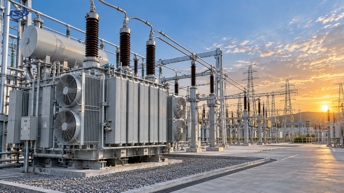
Cooling selection deserves particular attention. ONAN cooling offers simpler operation and lower auxiliary dependence, while ONAF can provide additional capacity through fans. The higher rating available with forced cooling may be valuable, but it depends on fan availability, control logic, auxiliary supply reliability, alarm settings, and maintenance. If the growth plan relies on ONAF capacity, the station design should treat cooling equipment as part of the capacity path rather than an optional accessory.
Impedance can change the answer even when MVA ratings look identical
Two transformers with the same rated power can behave very differently in a substation. Percentage impedance affects voltage drop, short-circuit current contribution, parallel-load sharing, and the performance of downstream protection equipment. Selecting impedance late in the process can force expensive revisions to switchgear ratings, cable sizing, relay settings, or busbar design.
Lower impedance generally reduces voltage drop but increases available fault current. Higher impedance helps limit fault current but can worsen voltage regulation and reduce the ability to support demanding loads. There is no universally correct value. The suitable range must be coordinated with the system fault study, voltage study, protection philosophy, and expected operating configurations.
Parallel transformer operation requires especially careful review. Rated voltage ratio, vector group, impedance magnitude, impedance angle, tap range, and tap position control all influence circulating current and load division. A new higher-capacity transformer paired with an existing smaller unit may not share load in proportion to its rating unless their electrical characteristics are compatible. In some arrangements, a replacement strategy is more reliable than trying to parallel mismatched units indefinitely.
Specify voltage control around the real network, not the nominal voltage
Nominal primary and secondary voltages are only the starting point. The transformer must maintain an acceptable secondary voltage across variations in source voltage, feeder loading, reactive power flow, and tap positions. This becomes more demanding where a substation supplies long feeders, large motors, converter-based loads, or a network with changing power-flow direction.
An on-load tap changer is often justified where voltage must be regulated while energized and load conditions vary materially. Its specification should cover the tap range, step size, control mode, voltage and current inputs, parallel-control requirements, blocking logic, remote interfaces, and monitoring expectations. A broad tap range is not automatically better. Wider range can affect impedance characteristics across taps and may be unnecessary if upstream voltage control already provides sufficient stability.
Where the transformer connects generation or renewable facilities, reverse power flow must be included in the control study. A tap-changing scheme that performs well for import-only operation may respond poorly when export changes the voltage profile. In smaller renewable step-up applications, an outdoor Transformer for Wind Power Generation can be specified with ratings from 630kVA to 5000kVA, 10kV, 20kV, or 35kV high-voltage options, and a 0.69kV low-voltage side. Such equipment is intended for wind turbine step-up and grid-connection duties, but its connection group, tap arrangement, cooling mode, and system study results still need to match the particular installation.
Losses and efficiency must be compared at the expected loading profile
A large power transformer has two principal loss components: no-load loss, present whenever it is energized, and load loss, which rises approximately with the square of current. This relationship changes the evaluation of capacity alternatives. A transformer selected far above the realistic load level may have unnecessary core loss throughout its life. Conversely, a unit operated close to its thermal limit for long periods can incur substantial load losses and may require forced cooling more often.
Compare guaranteed loss figures on a consistent basis and ensure that the stated reference temperature is understood. A meaningful technical evaluation considers the expected annual load shape, not merely a single efficiency number. Where tender procedures permit, capitalized-loss evaluation can make the tradeoff visible without assuming that the lowest-loss unit is always the right choice. The preferred design is the one that meets reliability and growth requirements while avoiding avoidable energy consumption over its intended operating range.
Losses also create heat that affects the station environment. Verify radiator clearances, airflow paths, enclosure effects, solar exposure, and whether nearby equipment can restrict cooling. A transformer may meet its thermal rating in open-air conditions yet require derating in a constrained installation. Outdoor placement does not remove this question; wind barriers, acoustic enclosures, high ambient temperature, and fouling of cooling surfaces can all reduce practical heat rejection.
Translate growth plans into physical and electrical interfaces
Capacity growth often fails at an interface rather than inside the transformer. A larger unit may have higher bushing current requirements, increased short-circuit forces, larger cable terminations, heavier transport weight, greater oil volume, and larger clearances. These details should be checked before the transformer rating is finalized, particularly in brownfield substations.
Review the following alongside the transformer datasheet:
- HV and LV bushing ratings, terminal arrangement, phase spacing, and conductor loads.
- Switchgear continuous current and short-circuit withstand ratings.
- Bus duct, cable, and cable-box thermal capacity at the upgraded MVA.
- Foundation loading, access route, lifting provisions, and installation clearances.
- Oil containment, fire separation, drainage, and local site requirements.
- Neutral grounding method, neutral current duty, and insulation levels.
- Protection CT locations, ratios, accuracy classes, and relay coordination after the fault level changes.
Short-circuit withstand capability should be explicitly specified rather than assumed from the MVA rating. The transformer must tolerate the mechanical and thermal stresses associated with the calculated system fault duty. This requires coordinated information from the network study: source fault level, impedance of connected equipment, operating configuration, fault-clearing time, and grounding arrangement.
Do not treat monitoring as a substitute for margin
Temperature indicators, winding hot-spot estimation, dissolved gas monitoring, bushing monitoring, and cooling-system alarms can improve operational visibility. They are valuable where loading is variable, contingency utilization is high, or maintenance access is limited. Yet monitoring does not add thermal capability or correct an unsuitable impedance value. It helps operators recognize developing conditions and manage the asset within its designed limits.
The monitoring package should align with the operating risk. A unit expected to run near its planned capacity, rely on forced cooling, or supply a critical load warrants clear alarms for oil temperature, winding temperature, cooling-stage status, oil level, pressure relief operation, and tap changer condition where fitted. Alarm thresholds need defined response actions; otherwise, the site may collect indications without a practical decision path.
Turn the specification into verifiable tender requirements
A robust specification separates mandatory electrical performance from preferred construction features and from project-specific interface information. It should state the rating at each cooling stage, voltage ratio, vector group, impedance and tolerance, insulation levels, tap changer requirements, loss guarantees, sound limits where relevant, short-circuit withstand requirements, temperature-rise limits, accessories, test requirements, documentation, and site conditions.
Factory testing should be tied to the specified design rather than treated as a generic formality. Routine tests confirm fundamental characteristics of the manufactured transformer. Where the duty is demanding, the purchaser may also need clearly defined requirements for type-test evidence, special tests, loss measurement, impedance measurement, induced-voltage testing, lightning impulse testing where applicable, and functional checks of control and cooling equipment. The test scope should correspond to the equipment rating, system importance, and contractual standard.
Before award, compare supplier submissions using a common technical schedule. Flag deviations in cooling ratings, impedance, loss values, tap range, guaranteed sound level, accessory scope, and transport dimensions. A proposal may appear compliant at headline MVA level while relying on a different cooling assumption or offering a materially different impedance. Those differences should be resolved before procurement, not discovered when protection settings and civil works are already fixed.
The final selection should leave usable operating margin after credible growth and contingency conditions are applied, while remaining coordinated with the network around it. That is the practical standard for a high-capacity substation transformer: not the largest unit that can be purchased, but the unit whose thermal, electrical, mechanical, and operational limits match the expansion plan with assumptions that can be tested and maintained.

Get a Quote
Regardless of whether you require general advice or specific support, we are happy to help you.
Send Us Your Inquiry Today

Jinshida Electric remains committed to contributing to global energy development through professional manufacturing and superior service.