





Sizing a Compact Substation Transformer for Load Growth and Ventilation
A compact substation transformer should be sized against the forecast coincident load and the thermal conditions inside its enclosure—not simply against today’s peak demand. A transformer with sufficient nameplate capacity can still run too hot if ventilation is restricted, solar exposure raises enclosure temperature, or nonlinear loads increase winding losses.
The practical decision is whether the selected rating can supply the expected load profile, including credible growth, within the manufacturer’s temperature-rise and loading limits. Buying a larger transformer does not automatically resolve poor cooling: its losses, physical dimensions, and airflow requirements must be checked as part of the complete substation arrangement.
Convert the load forecast into a credible operating duty
Start with measured demand where available. Interval data should cover representative production cycles, seasonal cooling demand, and operating conditions that could create the highest sustained load. A brief motor-starting event and a peak lasting several hours impose different requirements; neither should disappear into a single annual maximum.
For a balanced three-phase load, apparent power can be calculated as:
S (kVA) = P (kW) / power factor
Use true power factor where distortion is material, rather than displacement power factor alone. For loads with different power factors, aggregate active and reactive power before calculating total apparent power. Where significant harmonics are present, measured RMS current and harmonic spectra provide a better basis for thermal assessment than a simplified kW conversion.
Connected equipment ratings are not the same as coincident demand. Standby machinery, alternating production lines, and independently scheduled equipment should not automatically be added at full rating. Conversely, diversity assumptions become unsafe when operating changes cause previously separate loads to run together.
Growth should therefore be tied to identifiable additions: another production line, a planned charging installation, expanded HVAC capacity, or a documented increase in operating hours. Separate committed additions from uncertain expansion. Applying a blanket growth percentage and then adding full future equipment demand can count the same growth twice.
An illustrative calculation shows how the assumptions affect the result:
This makes a 1,000 kVA unit a candidate, not an automatic approval. The 0.90 factor is an example, not a universal enclosure derating rule. The selected transformer and enclosure combination must demonstrate that the assumed capacity remains available under the specified conditions.
Keep growth allowance separate from thermal derating
Growth allowance addresses uncertainty in demand. Thermal derating addresses reduced heat-rejection capability or additional heating. Combining them into one unexplained “safety margin” makes it difficult to determine whether the specification actually covers either problem.
A useful screening relationship is:
Required nameplate capacity ≥ forecast design demand / applicable available-capacity factor
However, temperature, altitude, enclosure effects, and harmonic loading cannot always be represented by independent factors that are multiplied together. Their interaction may require a manufacturer’s thermal calculation or test evidence. A capacity factor obtained for one enclosure geometry should not be transferred to another arrangement without justification.
The ambient temperature used in the assessment also needs a clear definition. Outdoor weather-station temperature is not necessarily the cooling-air temperature reaching the transformer. Louvers exposed to heated paving, nearby exhaust outlets, internal recirculation, and solar-heated enclosure surfaces can all alter the actual inlet conditions.
Specify the site’s maximum and relevant average ambient temperatures, altitude, solar exposure, installation arrangement, and expected loading cycle. Check these against the service conditions underlying the offered rating. At altitude, reduced air density affects cooling, while insulation clearances may require a separate assessment.
Harmonics deserve their own review. Rectifiers, variable-speed drives, and other nonlinear loads can increase winding eddy-current and stray losses beyond what fundamental-frequency current alone suggests. Provide the supplier with the expected harmonic spectrum, loading pattern, and phase imbalance. A generic spare-capacity percentage is not a substitute for this assessment.
Calculate ventilation from losses, not transformer kVA
The ventilation duty is driven by the heat released inside the enclosure. For a liquid-immersed transformer, the principal components are no-load loss and load loss, together with heat from low-voltage equipment, busbars, cables, and auxiliaries.
A preliminary heat estimate can be expressed as:
Heat release ≈ P0 + x2Pk + other internal losses
Here, P0 is no-load loss, Pk is the specified load loss at rated current, and x is the operating-current fraction of rated current. This approximation assumes broadly comparable voltage, waveform, and temperature conditions. Winding resistance changes with temperature, and harmonic-related losses require additional treatment.
Consider an illustrative transformer with 1.5 kW no-load loss and 10 kW rated load loss. At 80% rated current, estimated transformer heat release is:
1.5 + (0.8 × 0.8 × 10) = 7.9 kW
If other equipment contributes 1.1 kW, the internal heat load becomes 9 kW before considering solar gain and heat transfer through the enclosure. These values are calculation examples, not performance claims for a particular product.
For an initial airflow estimate:
Airflow (m³/s) = heat carried by ventilation (W) / [air density (kg/m³) × specific heat (J/kg·K) × air temperature rise (K)]
Using air density of approximately 1.2 kg/m³, specific heat of approximately 1,005 J/kg·K, and a 10 K exhaust-to-inlet temperature rise, removing 9 kW requires approximately 0.75 m³/s, or 2,700 m³/h. Actual design conditions may require different air properties.
This is a heat-balance estimate, not a complete ventilation design. It does not establish the acceptable transformer inlet temperature, prove adequate airflow around the tank or radiators, or account for local hot spots. Solar gain, enclosure conduction, and separate compartment ventilation must be included where relevant.
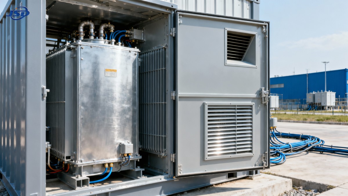
The physical airflow path matters as much as the calculated volume. Low-level intake and high-level exhaust openings can support natural convection, but performance depends on their vertical separation, free area, pressure losses, and internal obstructions. Intake air that travels directly to the outlet without passing the cooling surfaces provides little useful cooling.
Gross louver dimensions should not be treated as effective ventilation area. Screens, weather baffles, filters, and acoustic treatments reduce free area and add resistance. Natural ventilation requires a buoyancy and pressure-loss assessment or validated enclosure evidence; dividing the airflow requirement by an arbitrary air velocity is insufficient.
For forced ventilation, select fans using their operating point against the complete system resistance, not their free-air airflow rating. Define performance with dirty filters, the intended control sequence, and the response to fan failure. If full output depends on fans, the permissible load after losing ventilation must be explicit.
Check the transformer and enclosure as one thermal system
A transformer temperature-rise test outside the enclosure does not, by itself, validate performance inside a compact substation. Walls, partitions, cable routing, and adjacent switchgear change heat transfer and air circulation. Factory test evidence is useful only when its configuration is sufficiently representative of the proposed installation.
For prefabricated substations, IEC 62271-202 is relevant to assembly-level requirements, including thermal performance. IEC 60076-2 addresses temperature rise for liquid-immersed transformers, while IEC 60076-7 provides loading guidance for mineral-oil-immersed power transformers. The applicable editions, contractual requirements, and national adoption should be identified in the specification.
For an ester-filled design, confirm that the loading model and thermal limits are appropriate to the actual liquid and insulation system. Mineral-oil assumptions should not be transferred without supporting manufacturer guidance.
A candidate such as the 15kV/0.4kV Oil-Immersed Power Distribution Transformer illustrates why voltage ratio and a broad capacity range are only the starting point. For the selected rating and liquid option, request guaranteed losses, cooling designation, temperature-rise limits, dimensions, and evidence supporting operation in the intended enclosure. A family-level description cannot establish the installed thermal capacity of an individual configuration.
Likewise, a stated ingress-protection rating does not prove adequate cooling. Clarify whether it applies to the transformer, a terminal compartment, or the complete substation. Protective features and ventilation must be evaluated together, particularly where dust, moisture, or acoustic restrictions limit open airflow.
Distinguish sustained growth from short-term overload
Short-term overload capability is not permanent expansion capacity. Transformer temperature responds over time, so a temporary peak after a lightly loaded period is different from the same peak following several hours near rated load.
Any overload allowance should identify its initial load, ambient temperature, duration, cooling availability, hot-spot limit, and insulation-aging consequences. Top-oil temperature alone does not fully describe winding hot-spot temperature. A claim allowing 150% load for two hours should therefore not be used as a general sizing rule without the associated conditions and thermal justification.
Starting duty also needs a separate electrical check. Motor starting can create unacceptable voltage dips even where the thermal loading is acceptable. Transformer impedance, upstream source strength, cable impedance, and starting method determine the result. Increasing the rating may improve voltage support, but it can also increase available fault current and affect switchgear selection.
Resolve the decision with comparable evidence
The next larger rating should be evaluated against the same demand profile and enclosure conditions, not accepted merely because it offers more kVA. Compare guaranteed no-load and load losses across the expected operating cycle. A larger unit may reduce load losses at a given demand but introduce different standing losses, dimensions, and installation costs.
Before accepting a rating, the technical submission should connect:
- The forecast coincident demand, power factor, harmonics, and load duration.
- The selected transformer’s guaranteed losses and thermal limits.
- The enclosure’s tested or calculated heat-rejection capability under site conditions.
- The permissible loading when filters are dirty or ventilation equipment is unavailable.
- The voltage-drop, fault-current, and protection implications of the selected size.
Commissioning should establish a baseline for load, ambient temperature, cooling-air temperature, and the available transformer temperature indications. These records help distinguish actual demand growth from deteriorating ventilation when temperatures rise later.
The defensible choice is the smallest rating that meets the credible future duty under verified installation conditions—not the smallest unit that matches today’s demand, and not the largest unit that fits the available space. When thermal evidence is missing, adding capacity does not close the gap; the enclosure and cooling design still need to be demonstrated.

Get a Quote
Regardless of whether you require general advice or specific support, we are happy to help you.
Send Us Your Inquiry Today

Jinshida Electric remains committed to contributing to global energy development through professional manufacturing and superior service.