






Choose loop-feed when your network needs sectionalizing, alternate supply routing, or planned expansion. Choose radial-feed when one supply path meets your operational and reliability requirements.
A loop-feed pad mounted transformer does not automatically provide uninterrupted power. Its value depends on feeder topology, switching equipment, protection coordination, and an available alternate source.
For technical evaluators, the decisive question is whether additional primary connections support a defined operating strategy. Extra bushings alone cannot deliver the continuity your project requires.
This guide explains the practical differences, identifies the specifications that matter, and shows how to compare investment against restoration capability, maintenance needs, and future network growth.
What Actually Changes Between Loop-Feed and Radial-Feed?
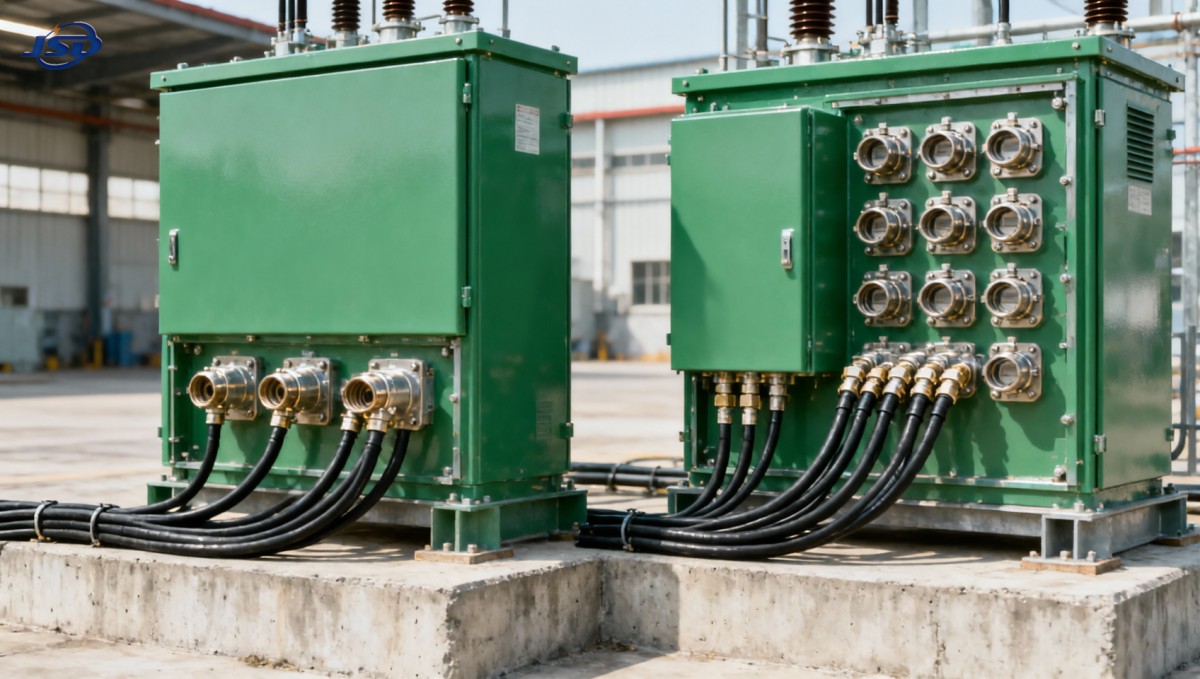
In a typical three-phase radial-feed arrangement, three primary connection positions serve one incoming feeder. The transformer supplies its secondary load through that single primary connection.
A typical three-phase loop-feed arrangement provides six primary connection positions: one set for incoming cables and another for outgoing cables continuing along the distribution circuit.
These paired connections commonly share electrically connected internal terminals. They do not necessarily include switches capable of isolating each cable segment or interrupting fault current.
The distinction concerns primary cable routing and connection provisions. It does not, by itself, establish different transformer efficiency, thermal performance, secondary voltage, or short-circuit impedance.
Actual construction varies by manufacturer, voltage class, connector rating, and purchasing specification. Confirm the terminal arrangement and switching schematic before treating either label as sufficient.
Does Loop-Feed Improve Reliability Enough for Your Load?
Loop-feed can reduce restoration time after certain upstream cable faults, provided operators can isolate the faulted section and energize healthy sections through another available path.
Consider several transformers connected along a normally open ring. A designated open point prevents continuous parallel operation while allowing supply restoration through approved switching sequences.
After locating a failed cable section, operators isolate it at suitable points. They can then close the appropriate open point to restore eligible downstream loads.
This process requires correctly placed switching devices, adequate alternate feeder capacity, compatible protection, and safe operating procedures. A six-bushing transformer alone cannot perform these functions.
The alternate route must also survive the initiating event. Two routes sharing vulnerable trenches or the same upstream supply may retain significant common failure exposure.
For radial-feed systems, an upstream fault typically disconnects downstream loads until repair or external transfer. That limitation may be acceptable where outages have manageable consequences.
Loop-feed also does not bypass a failed transformer winding. Restoring that transformer's secondary load requires another transformer, a secondary transfer arrangement, or another suitable supply.
Define reliability in measurable terms: acceptable interruption duration, loads requiring restoration, operator response time, and transfer capacity. These targets make configuration comparisons more useful.
Which Switching and Protection Details Determine Whether It Works?
Start by separating cable connections from switching functions. Specify which devices perform sectionalizing, load interruption, transformer isolation, and fault clearing, and where each device sits.
Loadbreak elbows permit particular operations within their ratings and prescribed procedures. They do not provide a universal substitute for dedicated switches or fault-interrupting equipment.
Deadbreak connectors require de-energized operation. Their presence can materially change restoration procedures, especially when your operational plan assumes quick field switching during feeder outages.
Internal switching options also vary. Request the actual schematic and ratings rather than assuming every loop-feed unit includes independent switches for both cable directions.
Transformer branch protection and feeder protection serve different purposes. Depending on construction, a transformer fuse may clear a winding fault while leaving through-feed connections energized.
Review coordination for every intended operating state, including normal supply, alternate supply, and maintenance conditions. Changed current direction and source impedance can alter protective-device performance.
Evaluate available fault current against connector, switch, bus, fuse, and transformer withstand ratings. Include future network reinforcement if it could increase fault levels during service.
A closed-loop operating scheme requires separate engineering assessment. Depending on source arrangements, it may introduce parallel supplies, circulating currents, and more demanding protection or switching requirements.
Require an operating diagram identifying normal open points, permitted switching sequences, interlocks, and grounding locations. This document connects equipment procurement with practical field operation.
Can the Alternate Feeder Carry the Restored Load?
An alternate path provides limited benefit if it cannot support transferred demand. Check feeder, cable, switchgear, and source capacity under the proposed restoration condition.
For illustration, a 1,000 kVA transformer at 20 kV draws approximately 28.9 A at rated load. Actual feeder loading includes every transformer supplied through that section.
If switching transfers several loads onto one feeder, assess their combined coincident demand. Do not size the alternate route from one transformer's rating alone.
Voltage drop can become the limiting factor before thermal capacity. Longer alternate routes may produce unacceptable primary or secondary voltage during peak demand or motor starting.
Study minimum and maximum fault currents after transfer. Reduced fault current may delay protection operation, while increased current may exceed equipment ratings or disrupt coordination.
Check transformer impedance, grounding arrangements, phase identification, and phase sequence. Where switching could parallel sources, assess synchronism, voltage compatibility, and utility restrictions before permitting closure.
If remote switching is proposed, include communications availability, control-power resilience, position indication, and operating authority. Automation requires a complete system design to shorten restoration reliably.
When Does Radial-Feed Offer Better Lifecycle Value?
Radial-feed often fits isolated facilities, small commercial loads, and distribution points where one supply route is sufficient. Simpler connections can reduce installation and inspection effort.
Its economic advantage depends on the whole installation. Compare cable quantities, terminations, civil works, switchgear, engineering studies, commissioning, and maintenance rather than transformer price alone.
Loop-feed costs can be justified where faster restoration reduces meaningful production losses or service disruption. Estimate those benefits using credible outage scenarios and actual operating capability.
For example, a manufacturing site with costly stoppages may justify sectionalizing and alternate feeder capacity. A lightly loaded remote facility may prefer a simpler radial arrangement.
Future expansion can strengthen the loop-feed case when additional distribution points are planned. Reserve cable routes, compartment space, switching positions, and feeder capacity accordingly.
However, extra terminals do not guarantee easy expansion. Physical access, utility approval, protection settings, and available network capacity may still constrain later additions or modifications.
Compare transformer losses separately from feeder configuration. Efficiency follows the specified core, winding design, loading, and evaluation method rather than the radial-feed or loop-feed designation.
How Should You Specify a Pad Mounted Transformer?
Prepare a specification around network operation and installation conditions. Asking only for “loop-feed” leaves important electrical, mechanical, and safety requirements open to differing interpretations.
- Electrical duty: State rated kVA, primary and secondary voltages, frequency, vector group, grounding, impedance, tap range, insulation level, and available fault current.
- Primary interface: Identify radial-feed or loop-feed connections, connector standard, current rating, loadbreak or deadbreak requirements, cable sizes, and required accessories.
- Switching and protection: Define switch functions, interrupting duties, fuse arrangements, coordination requirements, isolation points, normal open locations, and permitted operating states.
- Site conditions: Specify ambient temperature, altitude, corrosion exposure, flood risk, access clearances, enclosure security, cable entry, and applicable fire requirements.
- Acceptance evidence: Request drawings, schematics, applicable test reports, loss guarantees, equipment ratings, operating instructions, warranty terms, and relevant standards compliance.
Specify whether primary cable access and transformer access require separate isolation measures. On some loop-feed arrangements, through-feed connections remain energized after the transformer branch is isolated.
Request dimensions showing cable bending space and termination clearances. A technically suitable transformer can still create installation problems when the compartment conflicts with actual cable routing.
Choose applicable standards by equipment type and jurisdiction. IEC 60076 or relevant IEEE transformer standards may apply, alongside enclosure, connector, switching, and local utility requirements.
Where Does a Dry-Type Transformer Fit into This Decision?
Feeder topology and transformer insulation technology are separate decisions. A project can use a looped medium-voltage network while supplying a dry-type transformer through dedicated switchgear.
For indoor facilities, fire-sensitive locations, or projects limiting liquid-filled equipment, consider whether a dry-type installation better matches the site's environmental, ventilation, and enclosure requirements.
Jinshida Electric's 20kV Three-Phase Cast Resin Dry-Type Distribution Transformer is listed for 20 kV distribution applications, with 0.4/0.415 kV secondary options and application-specific customization.
The supplied range includes ratings from 50 to 5,000 kVA, with listed selections including 630, 1,000, and 2,500 kVA for different project load requirements.
This product should be evaluated as a dry-type transformer option within an engineered installation. The supplied information does not establish a conventional loop-feed pad-mounted assembly.
Its listed IP23 enclosure requires site-specific assessment for outdoor exposure. Confirm weather protection, accessibility, fire classification evidence, and any additional enclosure needed for the proposed location.
Verify published efficiency, losses, and forced-air overload capability against the selected rating and test conditions. Broad product claims cannot replace a guaranteed project-specific technical schedule.
Likewise, confirm certification documents for the exact model and destination market. Supplier quality-system certification and product conformity evidence support different aspects of a technical evaluation.
Which Configuration Should Your Team Approve?
Approve radial-feed when one primary supply route meets the service requirement and its expected outage consequences are acceptable. Document restoration arrangements and any future expansion constraints.
Approve loop-feed when alternate routing or sectionalizing delivers a defined operational benefit, and the network includes the switching, protection, capacity, and procedures needed to realize it.
Before procurement, validate the single-line diagram against realistic fault and maintenance scenarios. Require evidence that healthy loads can be restored safely within the target interruption duration.
The best pad mounted transformer configuration follows your network's operating requirements. Make the decision from demonstrated restoration capability and lifecycle value, then specify equipment accordingly.
