





Selecting Power Distribution Transformers for Data Centers With N+1 Redundancy
For an N+1 data center power architecture, a transformer selection error can turn a nominally redundant design into a single-point operational constraint. Matching primary voltage, secondary voltage, and nameplate kVA is necessary, but it does not establish whether the transformer can carry the facility after one parallel unit is unavailable, tolerate the expected power quality conditions, or remain serviceable without creating an outage window.
The practical starting point is simple: each transformer in an N+1 group must be evaluated against the load it will carry during a contingency, not only against its normal share of the load. A design with three transformers serving a two-transformer load may look redundant on a one-line diagram, yet still fail its intended purpose if the remaining units exceed their thermal, harmonic, or cooling limits after one transformer is isolated.
Technical evaluators selecting a power distribution transformer for data centers should therefore assess four connected issues: contingency capacity, loss and temperature behavior, electrical isolation and fault coordination, and the maintainability of the whole transformer arrangement. A stronger individual transformer does not automatically create a resilient system. The bus topology, protection scheme, physical layout, and operating assumptions determine whether redundancy is usable.
Start with the N+1 load case, not the normal operating case
N+1 means that the required load can continue to be served after the loss of one equivalent capacity element. In transformer systems, the interpretation depends on topology. A facility may use several transformers in parallel on a common low-voltage bus, separate transformer lineups feeding A and B paths, or modular transformer blocks assigned to power distribution units and downstream switchgear.
For parallel transformers, the most important calculation is the post-failure load per surviving unit. If two transformers are required to carry the critical demand and a third is installed as the “+1” unit, each remaining transformer must be capable of accepting approximately half of the designated contingency load after one unit is removed. That assessment needs to include more than IT load:
- UPS losses and rectifier input demand;
- cooling equipment that remains required during the event;
- lighting, controls, security, fire-life-safety interfaces, and auxiliary loads served from the same electrical path;
- future capacity that has already been committed in the capacity plan;
- transformer derating caused by ambient temperature, altitude, ventilation constraints, or harmonic loading.
A common mistake is to divide the measured average building load by the number of installed transformers. Data center electrical systems are designed around peaks, ramp events, maintenance transfers, and operating modes. The relevant question is whether the remaining transformer group can support the defined critical load at the worst credible operating condition, without relying on a short-duration overload assumption that conflicts with the expected repair or replacement time.
Short-term overload capability can be useful during controlled transfers, but it should not be treated as permanent N+1 capacity. Its availability depends on transformer temperature before the event, ambient conditions, insulation system, cooling arrangement, and manufacturer limits. A transformer already operating near its thermal limit has little useful margin when another unit trips.
Check capacity sharing before specifying equal kVA units
Identical ratings simplify parallel operation, inventory, and protection studies, but equal nameplate kVA alone does not guarantee balanced loading. Parallel transformers need compatible voltage ratios, vector groups, impedance values, and tap positions. Material differences in impedance can cause one transformer to carry a disproportionate share of current. The result may be a transformer that overheats while the group appears comfortably loaded on aggregate metering.
When transformers of different ratings are unavoidable, the review should establish how load will divide at normal and contingency conditions. This calls for actual impedance and ratio data, rather than a generic statement that units are “parallel capable.” The protection study should also confirm that the planned arrangement detects an internal transformer fault selectively and does not unnecessarily remove healthy capacity.
For A/B distribution architectures, a different risk often appears. The facility may have redundant transformer capacity overall while a particular downstream bus, UPS input, tie breaker, or feeder cannot accept the transferred load. N+1 at the transformer level is meaningful only when the switchgear and cable paths can deliver the remaining capacity to the loads that need it.
Efficiency matters most at the loads the site will actually see
Transformer efficiency is frequently discussed as a procurement comparison, but the operating profile matters more than a single headline value. Core loss remains present whenever the transformer is energized. Load loss rises with current and is particularly relevant where the transformer operates heavily loaded or carries substantial harmonic current. A large facility with multiple lightly loaded transformers may incur avoidable no-load losses; an aggressively loaded configuration may increase winding losses, temperature rise, and cooling demand.
The right balance depends on the expected utilization curve and the redundancy strategy. Some facilities keep every transformer energized and share load evenly to preserve immediate N+1 response. Others use sectionalized or staged arrangements in which capacity is energized as the load grows. The latter can reduce losses at low utilization, but introduces switching procedures, protection complexity, and a need to verify that a newly energized path is ready before it is required.
Evaluators should ask suppliers for loss data at the relevant operating conditions and use it in the facility energy model. The comparison should distinguish between no-load loss, load loss, impedance, temperature rise, and the assumed reference temperature. A proposal that looks favorable at full load can be less attractive if the facility will run for long periods at a substantially lower load factor.
Temperature performance has a direct reliability consequence. Data center transformer rooms can be affected by adjacent switchgear losses, constrained airflow, heat rejected by UPS equipment, and elevated outdoor temperatures for pad-mounted or enclosure installations. Transformer cooling must be reviewed as part of the room or enclosure design, including air paths, clearance, heat removal, fire separation requirements, and the effect of one unit being taken out of service.
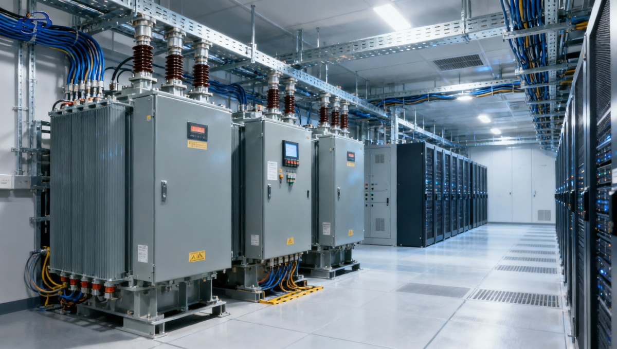
Low impedance is not automatically preferable. It can reduce voltage drop, but it can also increase available fault current at the secondary bus, affecting breaker ratings and arc-flash mitigation options. Higher impedance limits fault current but produces more voltage drop and can complicate motor starting or large step-load behavior. The appropriate value must be coordinated with the complete electrical system rather than selected as an isolated transformer preference.
Account for nonlinear loads and UPS operating behavior
Data centers contain a high concentration of power electronic loads. Modern UPS systems, servers, variable-speed drives, battery systems, and cooling equipment can produce or interact with harmonic currents depending on their topology and operating state. Even where upstream UPS rectifiers have good input-current performance, the transformer should not be assumed to see a purely sinusoidal, balanced load across all normal and abnormal modes.
Harmonics increase eddy-current losses and localized heating in windings, leads, and structural components. Neutral loading also deserves attention in low-voltage systems with substantial single-phase electronic loads. The transformer specification should state the anticipated harmonic spectrum or, where that is not yet available, define the information required from the electrical design team and major equipment suppliers before the final rating is frozen.
Several checks are useful during technical evaluation:
- Confirm the transformer is designed for the expected nonlinear load duty, rather than applying a standard rating without thermal assessment.
- Review the UPS manufacturer’s input characteristics for normal operation, bypass operation, charging, and recovery after a generator-supported event.
- Examine neutral conductor sizing, grounding arrangement, and zero-sequence behavior alongside the transformer vector group.
- Coordinate harmonic mitigation equipment with transformer impedance and upstream source impedance to avoid an unintended resonant condition.
- Verify voltage regulation during anticipated step changes, including transfer events and cooling-load restoration.
Isolation is also a system-level choice. Delta-wye configurations are commonly considered where isolation of certain zero-sequence components and establishment of a stable grounded secondary are required, but the correct vector group depends on the grounding plan, parallel-operating requirements, and protection philosophy. A mismatched vector group can prevent intended paralleling or create difficult fault-detection behavior. It should be selected early enough that the switchgear, relay settings, and cable design can be coordinated around it.
Backup generation changes the transformer review
The transformer must work correctly with the alternate source, not only with the utility supply. During a utility outage, generator voltage regulation, transient response, UPS rectifier behavior, and sequential load pickup can create conditions that differ materially from normal grid operation. The available fault current from a generator is often lower and decays differently than utility fault current, which may affect protective-device sensitivity and clearing time.
For smaller distributed backup blocks, a weather-protected generator package with intelligent controls, optional ATS integration, and remote monitoring can support the resilience plan when it is correctly coordinated with the transformer and downstream loads. For example, a Silent Canopy Diesel Generator Set may be relevant where outdoor installation, controlled transfer, noise limits, and sustained standby operation are part of the site constraints. Its suitability is still determined by the full emergency power study: transformer inrush, starting sequence, UPS recharge current, generator step-load capability, and the loads permitted to reconnect after transfer.
Transformer magnetizing inrush deserves particular attention in generator-backed systems. Energizing a transformer can create a high but temporary current demand, especially if switching occurs at an unfavorable point on the voltage waveform or residual core flux is present. On a strong utility source this may be manageable. On a generator source, it can produce a voltage dip, nuisance protective operation, or an unstable transfer sequence if the controls have not been coordinated.
Specify and test the intended restoration sequence. Decide which transformers remain energized, which loads are restored first, whether UPS charging is limited after transfer, and whether bus ties operate automatically or under controlled procedure. A one-line diagram without an operating narrative leaves too much room for assumptions during commissioning and later maintenance.
Design redundancy that maintenance teams can actually use
A transformer is only redundant if it can be isolated, tested, repaired, or replaced while the protected load remains served. This requires accessible primary and secondary isolation points, lockout provisions, sufficient cable slack or termination access, safe lifting and removal routes, and space to perform inspections without compromising adjacent live equipment.
Dry-type transformers are often selected for indoor proximity to loads because they avoid liquid dielectric fluid, while liquid-filled units may offer advantages in certain outdoor or higher-capacity arrangements. The decision should be based on the building’s fire strategy, location, environmental exposure, available footprint, cooling conditions, maintenance practices, and local code requirements. Treating one construction type as universally better usually obscures the actual design constraints.
Monitoring should support decisions, not merely collect values. Winding or hotspot temperature indication, enclosure temperature, fan status where applicable, load current, voltage, alarms, and protective relay events can help operators identify an abnormal condition before the remaining N+1 margin is consumed. The monitoring interface should align with the facility management or electrical power monitoring system, with alarm priorities that distinguish a device warning from a true reduction in redundancy.
Acceptance testing should verify the installed system as an operating arrangement. Beyond routine transformer tests, the commissioning plan should exercise loss of one transformer, transfer of the intended load path, protection selectivity where safe to test, generator-supported operation where applicable, and the expected alarm and monitoring sequence. The final operating procedures should state the load limits that apply when one transformer is unavailable. Those limits are often more valuable to operations staff than a nominal N+1 label.
A practical evaluation sequence
Begin with a defined critical-load envelope and an explicit contingency scenario. Then model normal loading, one-transformer-out loading, expected future loading, thermal derating, harmonic duty, fault current, and source-transfer behavior. Only after these conditions are established should the procurement team compare transformer ratings, construction options, loss values, accessories, and supplier documentation.
The strongest selection is rarely the unit with the largest nameplate rating or the lowest initial loss figure. It is the transformer configuration that retains capacity after a credible failure, remains within its electrical and thermal limits, coordinates with UPS and generator operation, and can be maintained without converting planned work into an outage risk. That is the standard a data center N+1 design needs to meet.

Get a Quote
Regardless of whether you require general advice or specific support, we are happy to help you.
Send Us Your Inquiry Today

Jinshida Electric remains committed to contributing to global energy development through professional manufacturing and superior service.