





Power Distribution Transformers for Data Centers: Managing Harmonics and PUE
A power distribution transformer for data centers must be evaluated against the actual electrical behavior of IT loads, not only against its nameplate kVA rating. Server power supplies, UPS rectifiers, variable-speed cooling drives, and power conversion equipment draw nonlinear current. That current produces harmonics which increase transformer heating, distort voltage, raise neutral loading, and add losses that work against Power Usage Effectiveness (PUE) targets. A transformer that appears adequately sized under a simple load calculation can run hotter than expected when harmonic current and restricted cooling are present.
The practical objective is to maintain stable voltage at downstream equipment while limiting avoidable losses in the electrical path. This requires a coordinated view of transformer impedance, winding configuration, harmonic spectrum, load growth, cooling conditions, conductor arrangement, and measurement points. Treating harmonics as a separate power-quality issue after the transformer has been selected often leads to unnecessary derating, additional filtering, or difficult changes in an energized facility.
Why nonlinear loads change transformer behavior
Linear loads draw current that closely follows the voltage waveform. Modern data center loads do not always behave that way. Switched-mode power supplies and rectifier front ends draw current in pulses. Even where equipment includes power-factor-correction circuitry, the current waveform can retain harmonic content, especially when multiple loads operate at light or changing load levels.
Harmonic current does not transfer power in the same useful manner as fundamental-frequency current, yet it still creates heating. In a transformer, this heating appears in several places: winding resistance, leakage-flux-related eddy losses in conductors, structural parts near the windings, core-related loss components, and terminals or connections with elevated current density. Higher-order harmonic components are especially relevant because eddy-current losses increase sharply with frequency. Therefore, total harmonic current alone is not enough to predict thermal duty; the order and magnitude of individual harmonics also matter.
A transformer operating at an acceptable total RMS current can still experience excessive temperature rise when the harmonic spectrum is severe. Conversely, a high current distortion reading does not automatically mean the transformer is unsuitable. The correct interpretation requires load data, transformer construction details, ambient temperature, ventilation, and the expected duration of the operating condition.
Separate the effects of power factor, distortion, and loading
Power factor is frequently used as a broad indicator of electrical quality, but it combines more than one effect. Displacement power factor describes the phase relationship between fundamental voltage and current. Distortion power factor reflects the effect of nonsinusoidal current. A facility can show a strong displacement power factor while still carrying harmonic currents that increase transformer losses.
Similarly, transformer loading expressed as a percentage of kVA rating does not state how much harmonic heating is occurring. A load profile should identify real power, apparent power, current THD, individual harmonic orders, phase balance, neutral current, peak-to-average load variation, and the simultaneous operation of UPS systems and cooling equipment. Measurements should cover representative operating states rather than a short period during steady demand. Startup, transfer events, bypass operation, staged cooling changes, and partial IT loading can produce different electrical signatures.
Transformer characteristics that affect harmonic performance
Selection begins with a realistic duty description. The specification should state the expected nonlinear load content and whether the transformer serves mainly UPS input equipment, UPS output distribution, mechanical loads, mixed loads, or a dedicated IT branch. These locations can have materially different current waveforms. Applying one generic transformer requirement across all distribution levels can result in unnecessary cost at one level and inadequate thermal capability at another.
Winding design influences harmonic loss performance. Conductors, strand arrangements, transposition methods, and winding geometry affect circulating and eddy-current losses. A design intended for nonlinear loading may use measures that reduce the influence of high-frequency leakage flux in the winding. Core and structural design also require attention, because stray flux can induce local heating in clamps, tank walls, and nearby metallic components.
Impedance must be considered as a system parameter rather than a standalone preference. Higher impedance tends to limit available fault current and can reduce the propagation of some disturbance currents, but it also produces greater voltage drop under load. Lower impedance supports voltage regulation and fault-current availability but can allow higher fault duty downstream. The selected impedance must work with upstream source strength, parallel transformers, UPS fault contribution, protective-device coordination, and permitted voltage variation at the point of use.
Winding connection determines the path available to zero-sequence and triplen harmonic currents. Triplen harmonics, such as the third and its multiples, are in phase across the three phases of a balanced three-phase system. In four-wire arrangements, they can add in the neutral instead of canceling. Delta-connected windings can provide a circulating path for certain triplen components, reducing their transfer to the other side of the transformer. That feature must be assessed alongside grounding requirements and the distribution topology; it is not a universal correction for all harmonic issues.
Electrostatic shielding between windings addresses a different problem. A shield can reduce the capacitive transfer of high-frequency common-mode noise between primary and secondary circuits. It does not remove low-order current harmonics or replace a transformer designed for the expected harmonic thermal duty. Confusing shielding with harmonic mitigation is a common specification error.
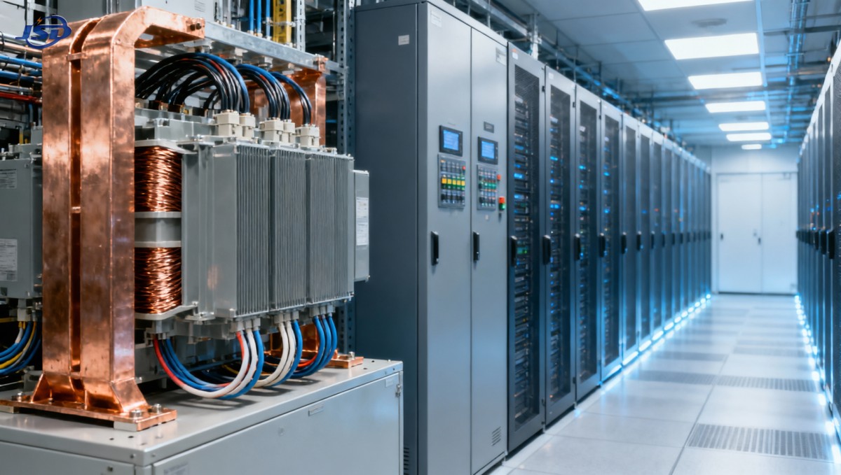
Harmonics, losses, and PUE measurement boundaries
PUE compares total facility energy with IT equipment energy. Transformer losses are part of the facility energy overhead whenever the measurement boundary includes them. Both no-load loss and load loss deserve attention, but they behave differently. No-load loss is present whenever the transformer is energized, including periods of low IT demand. Load loss rises with current and becomes more sensitive to harmonic content because of additional eddy and stray losses.
A lightly loaded transformer may therefore contribute a persistent energy penalty even though its temperature remains low. A heavily loaded transformer with distorted current can create a different problem: increased loss and thermal stress during high-demand intervals. Consolidating loads onto fewer appropriately rated transformers can reduce energized no-load losses, but only when redundancy requirements, contingency loading, fault isolation, maintenance access, and thermal margins remain acceptable.
Meter placement determines whether losses are visible. Comparing the transformer primary energy meter with a secondary meter over the same time interval reveals total transformer energy loss, provided meter accuracy, current-transformer polarity, and data intervals are verified. Comparing only facility input power with IT rack power gives a broader PUE result, but it cannot show whether rising electrical overhead comes from transformers, UPS systems, switchgear auxiliaries, or cooling plant changes.
Trend data is more useful than isolated readings. Track primary and secondary kW, kVA, power factor, voltage distortion, current distortion, phase currents, neutral current where applicable, ambient temperature, and transformer temperature indicators. A change in loss relative to comparable load may point to harmonic growth, a connection problem, cooling degradation, or a metering issue. The diagnosis should start by confirming the measurement chain before changing transformer settings or adding mitigation equipment.
When energy storage changes the electrical picture
Battery energy storage used for peak management, backup support, or microgrid operation introduces another power-electronic interface. Its power conversion system can alter harmonic current, reactive power behavior, short-duration loading, and bidirectional power flow at the transformer. The relevant question is not whether storage is present, but where it connects and how its control modes overlap with UPS, generators, and other conversion equipment.
For example, a containerized system with a 400 V three-phase four-wire AC output and a 500 kW power conversion system should be reviewed against the low-voltage bus fault level, transformer impedance, neutral arrangement, protection settings, and anticipated charging and discharge schedules. A 500kW/1MWh Air Cooling Container Energy Storage System using LiFePO4 batteries, intelligent air cooling, and a battery management system may be part of that analysis where backup or load-shaping functions are required. Its EMS or communication interface does not eliminate the need for coordinated harmonic measurements at the actual point of common coupling.
Charging during low IT demand can move transformer loading away from the profile used for original sizing. Discharge during a facility peak can reduce upstream loading, while also creating a different waveform at the low-voltage bus. If several converters have independently configured harmonic or reactive-power controls, their interactions should be verified under normal, transfer, bypass, and islanded states where those states are intended. Capacitor banks deserve particular caution because system resonance can amplify a harmonic frequency that was not prominent in an earlier operating mode.
Specification details that prevent later ambiguity
A request for a harmonic-capable transformer should define the electrical duty instead of relying only on broad labels. The expected load composition, harmonic current information, design loading profile, ambient conditions, altitude, enclosure arrangement, installation room ventilation, and required temperature-rise basis should be available before the thermal design is finalized. If measured harmonic data is unavailable, the specification should identify the connected equipment and expected operating modes so that assumptions are visible and reviewable.
- State whether the rating must be maintained under a defined nonlinear-load spectrum, rather than requesting a generic harmonic rating without a load basis.
- Include the intended vector group, neutral treatment, grounding arrangement, and whether the secondary serves three-wire or four-wire distribution.
- Identify tap range and tap position requirements. Voltage correction through taps cannot compensate for dynamic voltage distortion or excessive feeder drop.
- Define impedance tolerance where parallel operation, short-circuit coordination, or voltage regulation makes it significant.
- Require routine electrical tests and a documented review of no-load loss, load loss, impedance, insulation class, and temperature-rise data relevant to the ordered design.
There is also a difference between a transformer designed for nonlinear loading and a conventional unit that is simply oversized. Oversizing lowers fundamental current density and can create additional thermal margin, but it does not necessarily address frequency-sensitive eddy losses, neutral behavior, or system-level distortion. It also increases no-load loss exposure if the added capacity remains energized during low load. A purpose-designed winding arrangement paired with an appropriate rating is often a more defensible approach than selecting a much larger conventional transformer without a harmonic study.
Commissioning and condition monitoring
Before energization, verify nameplate data against the single-line diagram, phase rotation, winding connection, grounding points, tap position, torque records for bolted connections, and clearance around air inlets and outlets. Dry-type units installed in electrical rooms require their designed airflow path to remain unobstructed. Transformers placed near heat-producing switchgear, cable bundles, or UPS equipment can experience elevated inlet-air temperature even when the room sensor appears acceptable.
Baseline measurements should be captured after loads have stabilized and repeated after major capacity additions. Record measurements on both sides of the transformer where practical. Current-only measurements can miss voltage distortion; voltage-only measurements can obscure the source of harmonic current. Thermal imaging is valuable for identifying abnormal terminal or bus-joint heating, while winding temperature indicators and alarms show the overall thermal response. Neither replaces the other.
Alarm interpretation should consider operating context. A gradual increase in temperature at a similar load may indicate blocked ventilation, degraded cooling equipment, or a changing harmonic profile. A sudden temperature rise after electrical work suggests a connection, phase-loading, tap, or configuration issue. High neutral current should be investigated before neutral conductor or termination heating becomes visible. Repeated protective trips require waveform and coordination review rather than a simple increase in protective-device settings.
Reliable power quality and lower PUE both come from seeing the transformer as part of the electrical system. The most useful design decisions connect measured load behavior with winding capability, impedance, topology, thermal conditions, and energy metering. That connection prevents a nominally adequate transformer from becoming a hidden source of heat, voltage disturbance, and continuous energy loss.

Get a Quote
Regardless of whether you require general advice or specific support, we are happy to help you.
Send Us Your Inquiry Today

Jinshida Electric remains committed to contributing to global energy development through professional manufacturing and superior service.