





Selecting AVR Transformer Settings for Feeders With Rapid Load Changes
A feeder with rapid load changes should not be controlled by making the AVR “as fast as possible.” In most cases, that approach creates unnecessary tap operations, voltage hunting, and premature wear on the on-load tap changer. The practical objective is to keep customer-side voltage within the required operating range while allowing the regulator to ignore short, harmless fluctuations.
For a substation transformer with automatic voltage regulation, the setting package must be evaluated as a whole: voltage target, deadband, time delay, line-drop compensation, reverse-power behavior, and tap-change limits all influence one another. A setting that works well on a steady industrial feeder may behave poorly on a feeder supplied by variable-speed drives, arc furnaces, electric vehicle charging, or inverter-based generation.
Start with the feeder behavior, not the default AVR values
The first question is not “What deadband should be used?” It is “What is causing the voltage movement, how large is it, and how long does it last?” A regulator can only respond sensibly when its control logic reflects the electrical behavior of the feeder.
Load changes tend to fall into three practical groups. Short switching transients and momentary motor starts may produce a visible voltage dip but often do not justify a tap change. Repeating load cycles, such as batch-process equipment or large charging blocks, may require a measured response if the voltage remains outside the acceptable range. Sustained load transfers or generation changes need regulation, but the controller still needs to distinguish a real new operating condition from a temporary excursion.
Review interval data, event records, tap-position history, feeder current, reactive power, and voltage measured at the transformer bus. A simple maximum-and-minimum voltage record is not enough. It hides whether the feeder sees one long deviation or dozens of short deviations that happen to reach the same extremes. The latter is where poorly coordinated AVR settings usually cause excessive operations.
Set the voltage target around the point that matters
The AVR normally measures voltage at the transformer secondary bus, but the required service voltage may be at the end of a long feeder. If the transformer bus is held exactly at nominal voltage without considering feeder drop, remote customers can still experience undervoltage during high-current periods. Raising the target blindly, however, can overvoltage customers close to the substation when load falls.
Line-drop compensation can address this problem by estimating the feeder voltage drop from current and the feeder’s effective resistance and reactance. It is useful when feeder impedance is reasonably understood and the load distribution is stable enough for one compensation setting to represent most operating conditions. It is less reliable on highly branched feeders, feeders with major load transfers, or circuits where distributed generation changes the direction and location of power flow.
When the feeder has a critical remote point, evaluate the target against that point using representative high-load, low-load, and generation-export conditions. The preferred target is the one that keeps the widest useful portion of the feeder in range, not the one that makes the transformer bus look most precise.
Deadband and time delay should filter noise without hiding a real problem
Deadband defines the voltage range within which the AVR does not call for a tap change. Time delay defines how long the voltage must remain outside that range before the control acts. These are the primary settings for avoiding tap-change hunting.
A narrow deadband combined with a short delay makes the transformer highly responsive, but it also makes it sensitive to normal feeder variation. If voltage moves across the threshold during each load cycle, the tap changer may repeatedly operate and then reverse. This is not improved regulation; it is the control system reacting to conditions it cannot usefully correct.
A wide deadband or long delay has the opposite risk. It protects the tap changer from frequent operation but may leave a sustained voltage deviation uncorrected for too long. That can affect motor torque, sensitive electronic loads, contactor performance, and inverter operating limits.
There is no universal deadband or delay value because the correct setting depends on voltage sensitivity, feeder impedance, load cycling, and the mechanical capability of the tap changer. The more defensible approach is to use recorded operating data to identify the duration of normal excursions, then set the delay so ordinary short events do not trigger action. The deadband should be wide enough that one tap correction does not immediately produce a reverse command under expected variation.
Do not treat tap-changing speed as a substitute for feeder design
AVR control changes voltage in discrete steps. It cannot compensate every fast fluctuation without operating the tap changer frequently, and it cannot solve disturbances caused by poor power factor, inadequate conductor capacity, switching transients, or a weak upstream source.
Before tightening the control settings, separate voltage problems caused by steady-state drop from those caused by short dynamic events. Sustained voltage drop may justify a changed target, adjusted line-drop compensation, reactive-power support, or feeder reinforcement. A rapid dip caused by a large motor start may call for motor-starting measures, local support, or process coordination rather than a faster transformer response.
This distinction prevents a common mistake: using the on-load tap changer as the first remedy for every voltage complaint. The tap changer is a valuable control device, but its mechanical operation must be reserved for conditions that persist long enough to warrant a new voltage position.
Coordinate the transformer AVR with downstream and upstream controls
A substation transformer may be only one of several voltage-control devices on the same network. Downstream line regulators, switched capacitor banks, inverter voltage-reactive power functions, and an upstream transformer can all alter the voltage that the AVR sees. Without coordination, each device may respond to the others and create an operating cycle.
Define the control hierarchy before finalizing settings. In a typical arrangement, the upstream transformer maintains a broader supply-voltage objective, while downstream devices correct localized feeder conditions. Their voltage targets, bands, delays, and operating sequence should give each device a distinct role. Devices with faster or more local action should not be allowed to force repeated operations from a transformer control intended for slower, system-level regulation.
Capacitor switching deserves particular attention. A switched bank can create a voltage rise that prompts a transformer tap-down command; when the bank later switches out, the transformer may need to tap back up. Time coordination and appropriate control blocking or supervisory logic can prevent this sequence from becoming routine.
Reverse power and renewable feeders need separate evaluation
Feeders with photovoltaic generation can move rapidly between net import and net export as irradiance changes, inverter output changes, or local demand shifts. In these applications, a setting designed only for forward load flow may apply line-drop compensation in the wrong direction or regulate toward an unsuitable voltage target during export.
The evaluation should confirm how the AVR detects power direction, what it does during reverse flow, and whether compensation remains valid in each operating mode. Some networks use different voltage-control strategies during export; others rely on coordinated inverter reactive-power functions and limit the transformer’s automatic response. The appropriate method depends on the connection agreement, feeder topology, and available control architecture.
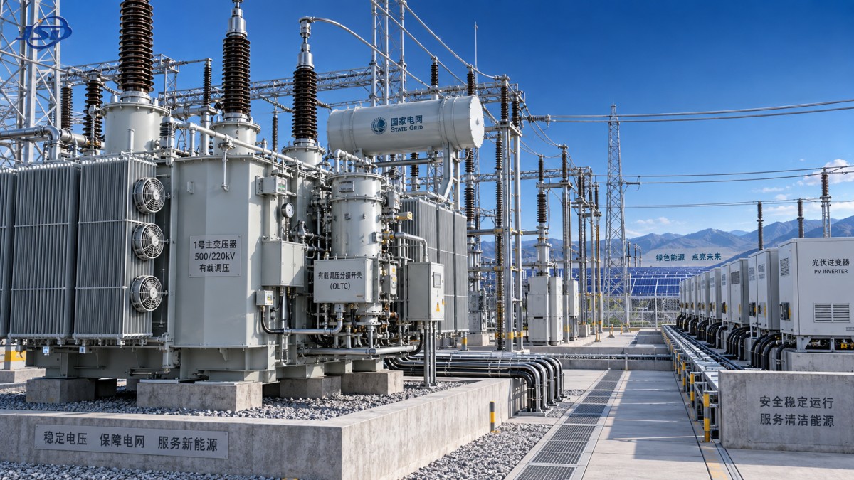
For photovoltaic projects, the transformer itself must also suit the electrical and environmental duty. A Step-Up Transformer for Photovoltaic Power Stations is intended to raise inverter output to the grid connection voltage and is available for outdoor three-phase applications with specified high- and low-voltage options. Its tap arrangement should be considered together with the site’s actual voltage-control scheme. A de-energized off-circuit tap range can establish the correct base ratio, but it does not replace an AVR or on-load tap-changing strategy when the feeder requires active voltage regulation.
Put operating limits into the settings review
Tap position alone does not show whether a control scheme is healthy. Review total operations, reversals, time spent at extreme positions, voltage exceptions, and controller alarms. A transformer that regularly reaches a tap limit may be showing an incorrect base ratio, excessive feeder drop, an unsuitable voltage target, or a network condition beyond the available regulation range.
Tap-change limits and maintenance planning should be part of the design decision, not an afterthought. High operation counts can increase maintenance demand and reduce the margin available for abnormal system conditions. Conversely, setting a restrictive operation limit without addressing the underlying voltage problem merely leaves the feeder unregulated after the limit is reached.
It is also important to check transformer loading and thermal behavior across the anticipated load profile. Voltage control affects tap position and current distribution, while loading affects the acceptable operating envelope. The AVR settings, transformer rating, cooling arrangement, and expected overload duty should therefore be reviewed together rather than by separate teams.
A practical commissioning sequence
- Establish the voltage range required at the relevant customer or interconnection points, not only at the substation bus.
- Collect representative load, voltage, power-factor, and tap-operation data across normal and changing conditions.
- Identify the duration and frequency of voltage excursions, separating transient events from sustained shifts.
- Set the base transformer ratio and target voltage for the most representative operating condition.
- Apply deadband and delay settings that reject normal short-duration variation while correcting sustained deviation.
- Validate line-drop compensation and directional behavior under both load import and generation export where applicable.
- Coordinate with capacitor banks, feeder regulators, and inverter controls, then review event records after commissioning.
Jinshida Electric Power Technology Co., Ltd. supports power transmission and distribution applications where transformer selection, manufacturing quality, and control requirements must work together. For rapid-load feeders, the useful technical discussion begins with the feeder profile and control philosophy, then moves to the transformer configuration and AVR setting range that can support it. That sequence produces a more reliable result than selecting a transformer first and attempting to correct unstable feeder behavior through aggressive control settings afterward.

Get a Quote
Regardless of whether you require general advice or specific support, we are happy to help you.
Send Us Your Inquiry Today

Jinshida Electric remains committed to contributing to global energy development through professional manufacturing and superior service.