





How Automatic Voltage Regulation Stabilizes Substation Output Voltage
A feeder may look stable at the start of a shift and then drift out of its preferred voltage band as production loads start, distributed generation changes output, or upstream grid conditions move. The effect is often noticed first at the low-voltage side: motors draw more current, contactors become less reliable, lighting changes, electronic controls alarm, or sensitive equipment begins operating near its allowable limits.
A substation transformer with automatic voltage regulation stabilizes output voltage by measuring the controlled bus voltage and automatically changing the transformer ratio when that voltage stays outside a defined target range. In most utility and industrial substations, this is done through an on-load tap changer (OLTC) controlled by an automatic voltage regulator (AVR). Rather than holding one fixed ratio all day, the transformer can raise or lower its effective turns ratio while energized, compensating for reasonably gradual changes in supply voltage and load-related voltage drop.
The operating problem AVR is designed to solve
Voltage at a transformer secondary is not determined by the transformer nameplate ratio alone. It is affected by the incoming voltage, transformer impedance, load current, power factor, feeder length, conductor condition, and the operating state of capacitor banks, generators, and other voltage-control equipment. A transformer that delivers acceptable voltage at light load can produce a lower value at the far end of a feeder when a large motor group starts or when reactive demand rises.
The opposite can happen when load suddenly decreases or local generation exports power toward the substation. Secondary voltage may rise even though the transformer itself has no defect. Manual tap adjustment can correct a sustained change, but it is too slow and too dependent on operator intervention for a system whose conditions vary through the day. AVR is intended to manage this repeating operational problem without requiring frequent manual changes.
The aim is not to create a perfectly flat voltage under every transient event. Short-duration disturbances, faults, switching transients, and rapid renewable fluctuations may require other protection or control measures. AVR provides controlled correction of sustained deviations within the tap range and response settings assigned to the transformer.
From voltage measurement to tap movement
An automatic voltage-regulation scheme has several elements working together: voltage sensing transformers, a regulator relay or controller, the transformer tap changer, a motor-drive mechanism, position indication, and interlocks. The controller compares the measured voltage with its programmed reference value. It then decides whether no action is needed, whether a time delay should begin, or whether a tap-change command is justified.
When measured voltage remains below the lower limit for longer than the selected delay, the controller commands a tap movement in the direction that raises the controlled voltage. When voltage remains above the upper limit, it commands movement in the opposite direction. Each tap step changes the ratio by a defined increment. The controller normally reassesses voltage after every operation rather than making an uncontrolled series of movements.
For a simplified relationship:
Secondary voltage ≈ primary voltage × selected transformation ratio − voltage drop through transformer and connected circuit.
Changing the tap changes the selected transformation ratio. Depending on transformer design and naming convention, a “raise” command may move the tap changer in a direction that increases the secondary voltage, even though the physical winding connection is described differently in documentation. Operators should always use the actual manufacturer’s tap-position chart and control logic instead of relying on the label alone.
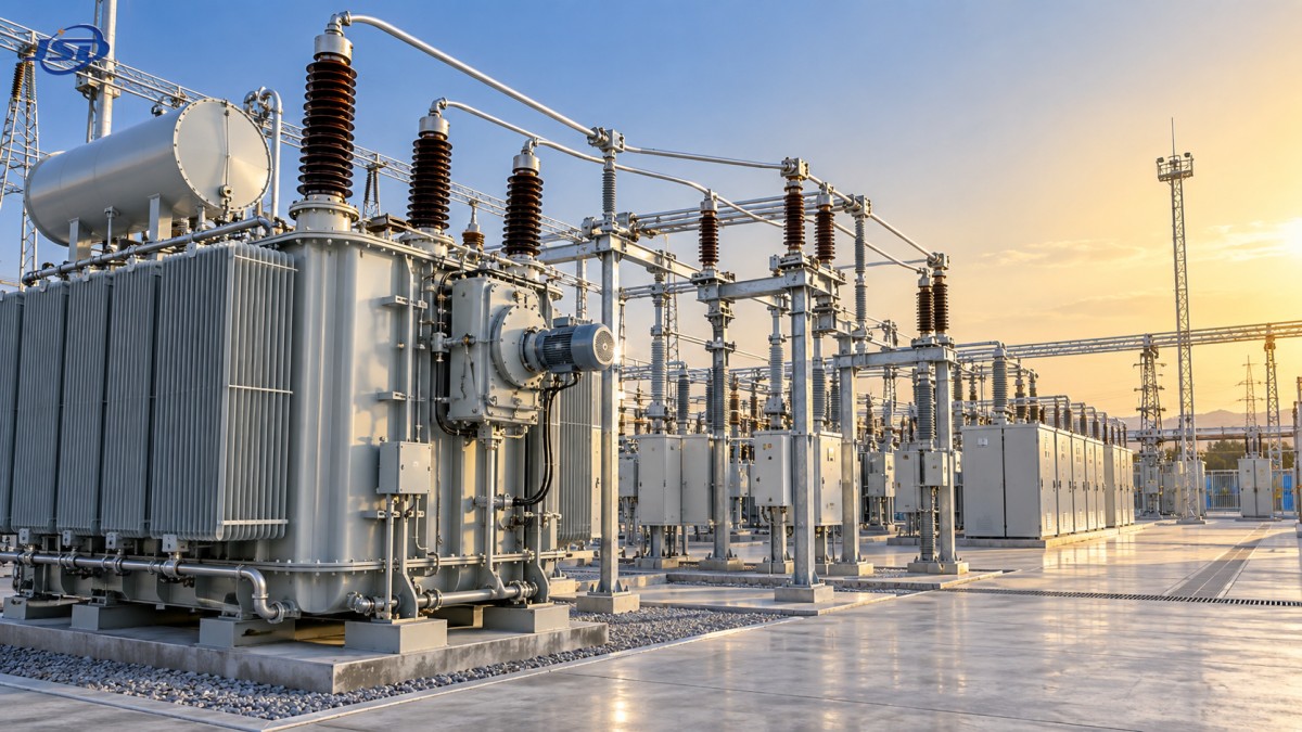
Most OLTC-equipped power transformers place the tap changer on the high-voltage winding because the current is lower there, making the switching duty more manageable. The OLTC transfers current between taps through a diverter switch arrangement so that the main circuit is not simply opened during a normal tap change. This is what separates on-load tap changing from an off-circuit tap link or de-energized tap switch.
Why the controller does not react to every voltage change
A regulator that acted immediately on every small fluctuation would cause excessive tap operations. That would increase mechanical wear, interrupt stable control behavior, and may lead to “hunting,” where the regulator repeatedly moves up and down around the target voltage. Effective regulation depends as much on settings as on the tap changer itself.
Voltage setpoint and bandwidth
The setpoint is the desired controlled voltage. The bandwidth, often called deadband, is the acceptable zone around that setpoint in which no tap command is issued. A narrow deadband can maintain closer voltage control but may produce more operations. A wider deadband reduces unnecessary movement but permits larger voltage variation. The correct setting depends on the connected system’s permitted voltage range, load pattern, downstream equipment sensitivity, and coordination with other regulating devices.
Time delay
Time delay prevents a brief voltage dip or rise from initiating a tap change. Motor starts, capacitor switching, and short switching events can alter measured voltage temporarily. If the voltage returns to normal before the delay expires, the controller does nothing. Intentional delay is therefore a control feature, not a sign that the regulator is failing to respond.
Line-drop compensation
Measuring voltage at the transformer terminals does not always show the voltage customers or process equipment receive at the end of a long feeder. Line-drop compensation allows the regulator to estimate feeder voltage drop based on load current and configured resistance/reactance values. The controller can then regulate toward a remote-load condition rather than only the local substation bus.
This function is useful but requires careful commissioning. Incorrect compensation values can make the regulator overcorrect or undercorrect. Feeder changes, altered conductor routes, new large loads, and different power-factor conditions can all make old settings less representative of the real circuit.
What operators should see during normal regulation
Under a changing but healthy load, voltage should remain within the intended operating band, and tap position should shift gradually rather than oscillate continuously. The controller display or supervisory system should show a sensible relationship between bus voltage, tap position, and command direction. When voltage falls under increasing load, taps should generally move toward the position configured to support voltage. When load reduces and voltage rises, movement should occur in the reverse direction after the delay criteria are met.
A tap position by itself does not prove correct operation. A transformer at a high or low tap position may be responding properly to a legitimate upstream condition. More useful evidence is the combination of:
- measured primary and secondary voltage;
- actual tap position and recent position history;
- load current, power factor, and feeder loading;
- AVR reference voltage, deadband, delay, and compensation settings;
- tap-change count and motor-drive alarms; and
- the status of parallel transformers, capacitor banks, and local generation.
Reviewing these values together helps distinguish a genuine voltage-control issue from a normal response to a changing network.
When output voltage still drifts despite automatic regulation
Operators sometimes assume that any unstable secondary voltage means the transformer AVR has failed. The cause may instead be outside the tap changer’s control range or inside the measurement and coordination system. Start with the symptoms before changing settings.
A disciplined response to a suspected AVR problem
Before operating controls manually, confirm that the voltage reading is credible. Compare the regulator measurement with a calibrated or independent metering source where site procedures allow. A failed voltage transformer fuse, loose sensing connection, incorrect scaling factor, or communication mismatch can cause the controller to react to an inaccurate value. Changing taps based on a false measurement can move the real system farther from the desired voltage.
Next, determine whether the deviation is temporary or sustained. Check the time relationship between voltage movement and load changes. A short dip associated with a large motor start may be expected and may not warrant a tap action. A persistent low-voltage condition after load has stabilized deserves investigation, particularly when the controller is at a limit or has issued an alarm.
Then inspect control state and mechanical feedback. Verify whether the AVR is in automatic, manual, local, remote, or blocked mode according to the installed scheme. Compare commanded and actual tap positions. A command indication without a corresponding completed position change can point to a motor-drive, limit-switch, interlock, auxiliary-contact, or tap-changer mechanism issue. Alarm codes and operation counters are valuable because they show whether the problem is electrical, logical, or mechanical.
Do not repeatedly force raise/lower commands to “see if it clears.” An OLTC is a switching mechanism with maintenance needs, and abnormal operation should be handled under the equipment procedure. Investigation may include the tap-changer motor drive, control wiring, diverter-switch condition, insulating medium condition where applicable, contact wear assessment, and functional testing by qualified personnel.
Coordination matters when more than one device regulates voltage
Substations rarely operate in isolation. An upstream transformer, downstream regulator, capacitor bank controller, generator excitation system, or inverter-based resource may all influence voltage. Poorly coordinated settings can make each device counteract another. For example, one regulator can raise voltage while another detects the rise and lowers its own tap, creating unnecessary movement without improving the final load voltage.
Parallel transformers need particular attention. Their voltage ratios, impedance characteristics, vector groups, tap ranges, and control strategy must be suitable for parallel operation. If independent AVRs are allowed to operate without appropriate coordination, a tap mismatch can create circulating current between transformers even when the external load is not large. Master-follower, circulating-current compensation, or other approved parallel-control methods may be used depending on the installation design.
Any setting change should be assessed against the full control hierarchy, not only the voltage measured at one panel.
Temporary substations require the same voltage-control discipline
Temporary electrical installations can experience particularly variable conditions: changing construction loads, intermittent mining equipment, restoration work after network damage, or new-energy equipment that is commissioned in stages. Fast deployment does not remove the need to confirm voltage ratio, protection settings, grounding arrangement, control mode, and the available method of voltage adjustment before energization.
Where a temporary distribution arrangement is needed, a trailer-mounted or skid-mounted Mobile Temporary Compact Substation may integrate a transformer, high- and low-voltage switchgear, protection devices, and controls in one outdoor package. Available configurations listed for this equipment include 500kVA to 1250kVA ratings, high-voltage options from 10kV through 35kV, a 0.4kV low-voltage side, three-phase 50Hz or 60Hz operation, and IP33 outdoor protection. Whether a particular unit includes OLTC-based automatic voltage regulation, or uses another voltage-adjustment arrangement, must be confirmed from its approved technical configuration; it should never be assumed from the compact-substation format alone.
For temporary service, operators should also watch for changes that invalidate initial settings: a longer temporary cable route, added generators, relocated loads, altered feeder impedance, or a shift from light daytime load to heavy evening operation. A regulation setting that was acceptable at commissioning may need a controlled review once the actual load profile is known.
Maintenance indicators that should not be ignored
AVR performance depends on both control accuracy and tap-changer condition. Rising tap-operation counts, delayed movements, incomplete position indications, repeated controller alarms, abnormal motor-drive behavior, or a sudden need for frequent manual correction should be recorded and evaluated. Trends are often more useful than one isolated reading because they show whether the regulator is becoming more active, less responsive, or mechanically inconsistent.
Routine work should follow the transformer and OLTC manufacturer’s maintenance requirements and the site’s safety procedures. This may include checking control power, terminal tightness, position indication, drive mechanism condition, protective interlocks, operation counters, and the condition of the switching compartment or insulating medium as applicable. A stable voltage display does not eliminate the need for inspection; the regulator may be maintaining voltage while approaching a mechanical or control fault.
Automatic voltage regulation works best when it is treated as a controlled system rather than a self-correcting black box. Accurate sensing, suitable deadband and delay, realistic feeder compensation, healthy tap-changing equipment, and coordination with neighboring voltage devices allow the transformer to hold output voltage closer to the required operating range while avoiding unnecessary switching.

Get a Quote
Regardless of whether you require general advice or specific support, we are happy to help you.
Send Us Your Inquiry Today

Jinshida Electric remains committed to contributing to global energy development through professional manufacturing and superior service.