





Rising Gas Levels in a 132 kV Power Transformer: What Should You Check?
Rising gas levels in a 132kv power transformer can signal developing thermal or electrical faults—but a single dissolved gas analysis (DGA) result rarely tells the whole story. For after-sales maintenance teams, the immediate question is practical: can the transformer remain in service while you investigate, or does the evidence justify urgent intervention?
The answer depends on which gases are increasing, how quickly they are changing, and what else is happening on the transformer. A suspicious laboratory result deserves attention, not an automatic diagnosis. Work through sampling quality, operating history, cooling performance, and protection indications together before deciding on corrective action.
Before interpreting the report, check for an immediate operating risk
Do not begin with gas ratios if the transformer already shows signs of distress. Review the control-room event log and speak with the operator. A gas increase accompanied by a Buchholz trip, sudden-pressure operation, differential protection operation, abnormal noise, smoke, or a major oil leak is a different situation from an isolated laboratory warning.
If protection has operated or an active internal fault is suspected, follow the site’s emergency procedures and involve the responsible protection and transformer specialists. Do not reset protection or re-energize solely because a subsequent DGA reading appears less concerning.
Establish the following before routine investigation continues:
- Whether any protection, temperature, oil-level, or cooling alarms have occurred.
- Whether the transformer is carrying unusual load or has experienced a recent overload.
- Whether oil and winding temperature indications are credible and within approved operating limits.
- Whether the latest gas increase is gradual, accelerating, or associated with a specific event.
Sampling and inspection must follow approved procedures for energized high-voltage equipment. Never open covers, loosen fittings, or access internal components as an informal troubleshooting step.
Make sure the increase belongs to the transformer—not the sampling process
A maintenance team can lose valuable time investigating a fault that exists only in the sample record. Before interpreting a change, compare the new report with previous results from the same oil compartment and sampling point.
Check the asset identification, sample date, gas units, laboratory method, and fluid type. Confirm whether the result came from the main tank, a separate on-load tap changer (OLTC) compartment, or an online monitor. These sources are not interchangeable.
Then review how the sample was collected. Was the valve flushed adequately? Was an approved gas-tight container used? Were air bubbles present? Was the sample exposed to unnecessary delay or poor handling? Changes in sampling technique can weaken comparisons, particularly at low concentrations.
For an unexpected result without corroborating warning signs, arrange a prompt confirmation sample using the site’s sampling procedure, consistent with IEC 60475 or the applicable equivalent. Where possible, retain the same sampling point and laboratory method. However, do not delay urgent operational action just to obtain a second sample when protection events or rapidly worsening conditions already indicate significant risk.
Account for anything that changed the oil baseline
Oil replacement, topping up, filtration, vacuum degassing, and repairs can all change dissolved gas concentrations. A decrease after treatment does not prove that the fault source has disappeared; gas generation may resume afterward.
Record these activities alongside the DGA history. Also check whether the insulation liquid is mineral oil or a natural ester. Fluid chemistry affects gas generation and interpretation, so mineral-oil criteria should not be transferred uncritically to ester-filled equipment.
Which gases are rising—and what could that pattern mean?
Read the complete gas pattern rather than treating one gas as a fault label. The following associations help direct an investigation, but none establishes the location or severity of a fault by itself.
A new, confirmed acetylene increase in main-tank oil deserves prompt specialist review, especially with rising hydrogen or protection indications. Yet declaring “internal arcing” from one trace measurement is not sound practice. Residual gases from an earlier event, sample contamination, and oil-compartment arrangements must also be considered.
Likewise, the carbon dioxide-to-carbon monoxide ratio should not be used alone to diagnose paper overheating. Insulation age, oil processing, oxygen exposure, and fluid chemistry can affect the picture. Furan testing may provide supporting evidence for cellulose condition, but its interpretation also depends on oil history and insulation materials.
For a 132 kV power transformer, the trend often matters more than the snapshot
A relatively high gas concentration that has remained stable for years may represent a historical condition. A lower concentration that rises sharply over a short interval may indicate an active developing problem. Both the absolute level and the rate of change matter.
For comparable samples, calculate the average concentration change:
Average change rate = (latest concentration − previous concentration) ÷ elapsed days.
If a gas rises from 40 ppm to 100 ppm over 30 days, the average increase is 2 ppm per day. This calculation describes the observed trend; it is not a universal alarm threshold or a direct measurement of total gas production.
Interpret the rate with care. Unequal sampling intervals can conceal acceleration. Oil treatment, fluid loss, gas release into a headspace, and changing oil temperature can affect measured concentrations. A difference close to laboratory uncertainty should not be treated as a precise generation rate.
Use the applicable utility criteria, manufacturer guidance, and current standards such as IEC 60599 or IEEE C57.104 within their stated scope. Voltage class alone does not provide a safe universal gas limit. Loading history, insulation liquid, transformer design, and baseline condition all matter.
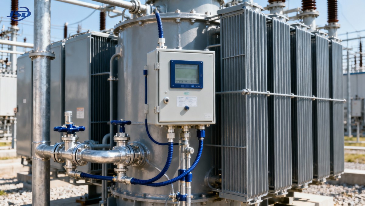
Connect the gas trend to what happened on site
The most useful investigation record places DGA results and operating events on one timeline. Plot the relevant gases against load, ambient temperature, top-oil temperature, winding temperature indication, cooling status, and tap changer activity. Look for a change that began before—not merely after—the gas increase.
Cooling and load: look beyond the temperature display
Check fan and pump availability, automatic start settings, control supplies, contactors, and alarm history. Where forced oil circulation is fitted, verify actual circulation through approved checks rather than assuming that a running motor proves adequate flow.
Inspect for obstructed radiator airflow, fouling, leakage, and incorrect valve positions. A radiator bank isolated after maintenance can quietly reduce cooling capacity. High ambient temperature, sustained overload, or abnormal harmonic loading may compound the problem.
Compare temperature readings with calibrated references where feasible. A faulty sensor can hide overheating, while a normal top-oil reading does not exclude a localized hot connection inside the tank. Winding temperature indicators may estimate rather than directly measure the hottest point.
Connections, bushings, and tap changer activity
Review accessible terminals and bushings for evidence of heating, leakage, discoloration, or abnormal thermal patterns. Thermal imaging should be performed at safe distances under approved site procedures. External heating can reveal a connection problem, but it cannot rule out an internal fault.
For the OLTC, check operation counts, recent maintenance, switching alarms, and whether its oil system is separate from the main tank. Switching gases may be expected in certain OLTC designs; their appearance in the main tank requires an explanation, not an assumption that the result is harmless.
Recent through-faults, lightning events, switching disturbances, and abnormal vibration also belong in the timeline. These details help specialists decide whether further electrical testing or internal inspection is warranted.
Choose the next action from the combined evidence
Maintenance decisions should be proportionate to risk, not driven by a single color-coded laboratory flag. Use three practical pathways, with final decisions made by the asset owner and authorized technical personnel.
- Confirmed but slow change, with no supporting abnormalities: consider continued operation under an approved monitoring plan. Set the next sampling interval according to the trend and applicable guidance, and specify what change will trigger escalation.
- Persistent or accelerating change, with possible thermal evidence: investigate cooling and loading promptly. Authorized load reduction, closer temperature monitoring, repeat DGA, and specialist review may be appropriate while the cause is assessed.
- Rapid gas growth, concerning discharge patterns, or protection operation: seek immediate operational and engineering assessment. An outage or isolation may be necessary under site procedures; continued operation should not be presumed acceptable.
Additional tests should answer a defined question. Depending on the evidence, specialists may recommend moisture and oil-quality testing, bushing capacitance and dissipation-factor measurements, winding resistance, insulation assessment, or targeted partial-discharge investigation. Many tests require an outage and controlled conditions; ordering every available test rarely improves diagnosis.
Online DGA can be useful when a developing trend needs closer observation, but confirm which gases the monitor measures and review its calibration status. A hydrogen-only monitor cannot provide the same diagnostic picture as a multi-gas laboratory analysis.
Close the loop: prove that the intervention worked
After repairing cooling controls, correcting connections, changing operating conditions, or completing internal work, establish a documented post-intervention baseline. Follow-up sampling should show whether the gas trend stabilizes, continues, or accelerates. If degassing was performed, distinguish the immediate removal of gas from the subsequent rate of renewed accumulation.
For replacement or modernization planning, Jinshida Electric Power Technology Co., Ltd.’s 110kV Oil-Immersed Transformer provides a relevant reference for oil-immersed equipment used in substations, industrial systems, and renewable-energy grid connections. It is not automatically interchangeable with a 132 kV unit: system voltage, highest voltage for equipment, insulation coordination, capacity, cooling arrangement, and liquid selection require project-specific confirmation.
Give the manufacturer or service team a concise evidence package: nameplate data, compartment details, fluid type, complete DGA history, sampling records, load and temperature trends, protection events, and maintenance history. This is far more useful than forwarding one report marked “high gas.”
The goal is not simply to bring a number down. It is to determine whether an active fault exists, control the operating risk, and verify that corrective work has addressed the cause. For after-sales teams responsible for a 132 kV power transformer, that evidence-led approach makes the next decision clearer—and easier to defend.

Get a Quote
Regardless of whether you require general advice or specific support, we are happy to help you.
Send Us Your Inquiry Today

Jinshida Electric remains committed to contributing to global energy development through professional manufacturing and superior service.