





Power Distribution Transformer for Solar Farms: Sizing for Inverter Block Loads
Power Distribution Transformer for Solar Farms: Sizing for Inverter Block Loads
Selecting the right power distribution transformer for solar farms is essential for matching inverter block loads, minimizing energy losses, and maintaining reliable plant performance.
For project managers and engineering leaders, accurate transformer sizing directly affects capital costs, grid compliance, operational stability, construction schedules, and long-term project returns.
This guide explains how to size capacity, select voltage ratings, evaluate losses, and specify protection features for utility-scale photovoltaic inverter blocks.
Start with the Inverter Block, Not the Plant Nameplate
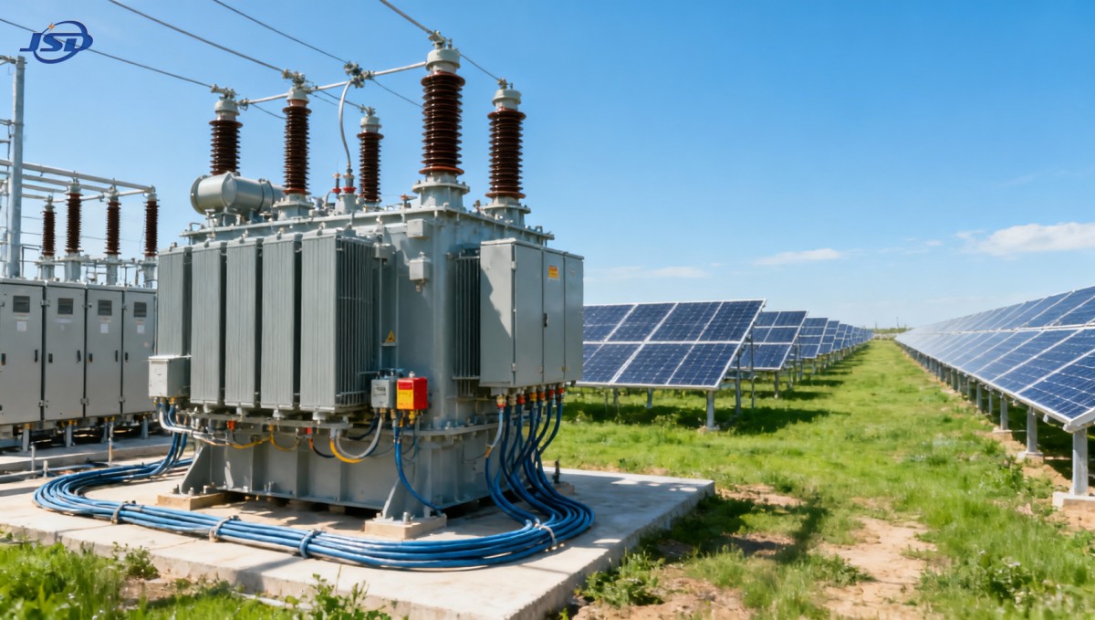
The core sizing question is straightforward: can the transformer continuously handle the maximum expected AC output of its assigned inverter block?
A solar plant may have a large DC nameplate rating, but transformer selection should normally begin with inverter AC capacity, operating power factor, and grid requirements.
For example, a 5 MWdc solar block may use 4 MWac of inverter capacity. Its transformer must be evaluated against the AC export limit.
Project teams should avoid selecting transformer capacity directly from module wattage. DC oversizing is common, while transformer loading follows the inverter-side AC output.
A practical starting calculation is transformer kVA equal to inverter MW divided by the minimum required operating power factor, plus justified design margin.
If a 4 MW inverter block must operate at 0.95 power factor, the minimum apparent power requirement is approximately 4.21 MVA before margin.
Where reactive power support is required, a transformer that appears adequate at unity power factor can become undersized during grid-support operation.
For this reason, the power distribution transformer for solar farms should be specified using both active power export and reactive power capability curves.
Calculate Capacity for Continuous Duty and Site Conditions
Transformer nameplate capacity is not the same as guaranteed usable capacity under every installation condition. Ambient temperature, altitude, cooling method, and enclosure arrangement matter.
Solar sites often experience high daytime temperatures precisely when generation reaches its peak. This makes thermal assessment more important than annual average loading.
Outdoor transformers installed near inverter stations may face direct solar radiation, restricted airflow, dust accumulation, and elevated ground temperatures around equipment pads.
For conventional oil-immersed units, ONAN cooling may be sufficient for standard loading, while ONAF cooling can provide additional capacity when forced-air fans operate.
However, relying on forced cooling as the only means of meeting normal plant output can increase maintenance exposure and reduce operating flexibility.
Project specifications should define whether the required capacity applies under natural cooling only, forced cooling, or both normal and contingency operating conditions.
Altitude also affects cooling performance. At higher elevations, lower air density reduces heat dissipation and may require transformer derating or a revised thermal design.
Ask the manufacturer to confirm the rated capacity at the project’s actual maximum ambient temperature, altitude, and solar exposure conditions.
A modest capacity margin is usually sensible, but excessive oversizing increases initial equipment cost and may raise no-load losses across the asset life.
Use the Right Margin Instead of Arbitrary Oversizing
Many projects add a generic 20 percent capacity margin without checking whether it addresses a real operating condition. That approach can waste capital.
A better margin reflects defined uncertainties: inverter overload capability, required reactive power output, temperature derating, future expansion, and contingency loading scenarios.
Inverter manufacturers may permit short-duration overload operation, but transformer selection should distinguish temporary overloads from continuous export requirements.
Solar clipping can also influence decisions. A DC-to-AC ratio above one does not automatically require a larger transformer if inverter AC output remains capped.
Conversely, projects designed for battery integration may require additional transformer capacity because charging and discharging profiles can extend high-load operating periods.
Expansion provisions should be deliberate. If a future inverter block is likely, evaluate a larger transformer against a separate future transformer and switchgear bay.
The preferred option depends on land availability, collector topology, loss economics, outage risk, and the cost of modifying medium-voltage infrastructure later.
Document the chosen margin in the design basis. This helps procurement teams compare supplier proposals on equivalent technical assumptions rather than headline kVA alone.
Match Low-Voltage and Medium-Voltage Interfaces Precisely
Voltage selection is a coordination exercise between inverter output, transformer impedance, collector system voltage, utility interconnection requirements, and equipment availability.
Common low-voltage inverter outputs include 0.4 kV and 0.69 kV, while medium-voltage collector systems may operate at 10 kV, 20 kV, or 35 kV.
The transformer ratio must match the actual inverter terminal voltage under normal operation, not merely a nominal value copied from an early project concept.
Voltage mismatch can reduce available export power, complicate inverter control, and create avoidable commissioning issues when the plant first synchronizes with the grid.
Tap settings are equally important. Off-circuit taps such as plus or minus 2 times 2.5 percent can help align the secondary voltage with site conditions.
Tap selection should consider collector feeder voltage drop, expected grid voltage range, inverter operating limits, and reactive power dispatch requirements.
For many photovoltaic projects, Step-Up Transformer for Photovoltaic Power Stations configurations can support low-voltage inverter output and medium-voltage collector connection within one coordinated package.
Specified voltage ratings should also identify the applicable frequency. A 50 Hz transformer cannot simply be assumed suitable for a 60 Hz network without technical confirmation.
Choose Vector Group and Grounding for Protection Coordination
Vector group selection affects fault behavior, harmonic circulation, grounding arrangements, and the ability of protection systems to detect and isolate abnormal conditions.
Dyn11 is frequently used where a delta-connected medium-voltage winding and grounded wye low-voltage winding support inverter-side grounding and harmonic management.
Yyn0 may suit other grounding or network requirements, but it should not be selected solely because it is available from a preferred supplier.
The project electrical study should define neutral grounding requirements, earth-fault protection philosophy, and expected zero-sequence current paths before finalizing the transformer vector group.
Solar inverters have different fault-current characteristics from synchronous generators. Protection settings must account for limited and controlled inverter fault contribution.
A transformer with the wrong winding connection can complicate earth-fault detection, create nuisance trips, or leave parts of the collector system inadequately protected.
Project managers should require coordination between transformer supplier data, inverter manufacturer information, relay settings, and utility protection requirements before equipment release.
This review is particularly important when multiple inverter blocks connect to a common collector feeder or a shared medium-voltage substation.
Evaluate Impedance, Harmonics, and Short-Circuit Duty Together
Transformer impedance influences voltage regulation, fault-current levels, parallel operation, and the behavior of inverter blocks during grid disturbances or switching events.
Higher impedance can limit fault current, but it also increases voltage drop at load. Lower impedance improves regulation while potentially increasing equipment fault-duty requirements.
The optimum impedance is therefore project-specific. It should be chosen through system studies rather than copied from a standard transformer schedule.
Harmonic performance is also relevant because inverter-based generation introduces switching-related harmonic currents and may operate across varying output levels throughout the day.
Modern inverter filters reduce harmonics substantially, but transformer winding design should still tolerate the expected harmonic spectrum without excessive heating or accelerated insulation aging.
Require harmonic information from the inverter vendor, including total harmonic distortion, individual harmonic limits, switching frequency, and operating conditions at maximum output.
Copper windings can support low losses and robust thermal performance when combined with an appropriate conductor design, insulation system, and specified temperature-rise limit.
Short-circuit withstand capability should meet applicable system fault levels and utility requirements. This includes both thermal and mechanical withstand performance during fault events.
Compare Losses as a Lifetime Cost, Not a Catalogue Number
Transformer losses affect plant revenue every day, even when output is modest. The key distinction is between no-load loss and load loss.
No-load loss occurs whenever the transformer is energized, including nighttime hours. Load loss rises with current and becomes most significant during high generation periods.
A solar plant has a distinctive loading profile, so loss evaluation should use annual energy simulations rather than assume a constant full-load operating condition.
For projects with long energized periods and variable daytime output, no-load loss can have material financial impact over twenty or more operating years.
Load loss should be assessed against expected irradiance distribution, inverter loading curves, ambient temperature, and the transformer’s operating cooling mode.
Procurement comparisons should convert guaranteed losses into annual energy cost using the project’s expected generation profile and a transparent electricity value assumption.
This method can justify a higher initial price for a lower-loss transformer where recovered energy value exceeds the incremental capital cost over the project life.
Request guaranteed loss values, test tolerances, and consequences for non-compliance in the purchase specification. Generic efficiency claims are not enough for investment decisions.
Specify Protection, Monitoring, and Outdoor Reliability
Solar farms are often remote, unmanned, and exposed to harsh weather. A power distribution transformer for solar farms must be designed for reliable outdoor operation.
Core protection typically includes surge arresters, temperature indicators, pressure relief devices, oil level indication, and appropriately coordinated medium-voltage and low-voltage protection.
Where project availability targets are demanding, online monitoring can provide useful visibility into oil temperature, winding temperature, moisture, dissolved gas, and cooling fan status.
Monitoring should be selected according to operational value. More sensors are not automatically better unless data is integrated into the plant monitoring and maintenance workflow.
Environmental conditions should be stated explicitly: minimum and maximum ambient temperatures, humidity, salt contamination, dust, wind, seismic requirements, and corrosion category.
For coastal or desert sites, enclosure coating, radiator protection, bushing selection, gasket materials, and cooling-air pathways can materially influence service life.
Outdoor installation also requires practical access for inspection, oil sampling, fan replacement, cable termination, and safe isolation during planned maintenance activities.
IEC 60076 compliance provides a useful baseline, but project specifications should add site-specific requirements rather than relying on the standard alone.
Build Procurement Around Verified Inputs and Acceptance Tests
Transformer procurement should begin with a controlled technical data sheet that defines capacity, voltage ratio, vector group, impedance, losses, taps, cooling, and insulation requirements.
It should also identify system short-circuit levels, grounding method, ambient conditions, altitude, applicable standards, accessory requirements, and interface responsibilities.
Do not leave critical parameters open for supplier interpretation. Ambiguous specifications often produce technically compliant equipment that does not fit the project’s operating assumptions.
Factory acceptance testing should verify ratio, vector group, winding resistance, insulation performance, impedance, no-load loss, load loss, and functional operation of specified accessories.
Where schedule risk is high, project managers should review drawing approvals, material lead times, test dates, shipping dimensions, and installation lifting requirements early.
Transport planning matters for larger units. Road restrictions, foundation capacity, crane access, oil handling, and delivery sequence can affect construction productivity and project milestones.
Commissioning plans should include insulation testing, oil checks where applicable, protection relay verification, phasing confirmation, tap position checks, and controlled energization procedures.
A complete handover package should include test reports, drawings, manuals, recommended spare parts, warranty terms, and maintenance requirements for the operations team.
Make the Final Selection Based on Plant Economics and Reliability
The best transformer is rarely the lowest-cost option or the largest available rating. It is the unit aligned with actual inverter duty and site constraints.
For project managers, the decision should balance first cost, electrical losses, thermal headroom, compliance risk, maintenance needs, construction practicality, and future operating flexibility.
Begin with verified inverter AC output and reactive power requirements. Then apply site derating, system studies, voltage coordination, and financially justified loss evaluation.
A well-specified transformer protects generation revenue by avoiding thermal limitations, voltage problems, avoidable outages, and expensive late-stage design changes.
When evaluating a power distribution transformer for solar farms, require suppliers to demonstrate fit against the project design basis rather than provide only standard catalogue ratings.
That discipline gives engineering leaders a clear basis for selecting equipment that supports grid compliance, dependable plant operation, and long-term solar asset performance.

Get a Quote
Regardless of whether you require general advice or specific support, we are happy to help you.
Send Us Your Inquiry Today

Jinshida Electric remains committed to contributing to global energy development through professional manufacturing and superior service.