





Oil-Cooled High-Voltage Transformers: Selection Factors for Outdoor Grid Projects
Start with the operating duty and the point of connection, then work outward to the transformer design. An oil cooled high voltage transformer for an outdoor grid project must be selected as part of a system: source voltage, grid voltage, expected loading pattern, site climate, protection philosophy, cable arrangement, and maintenance access all influence the correct specification. A unit that matches the nominal voltage and kVA rating can still perform poorly when its insulation level, tap range, cooling arrangement, or terminal configuration does not match the actual installation.
The first decision is whether the transformer is serving a relatively stable feeder, a heavily fluctuating industrial load, or a variable renewable-energy source. These duties create different thermal and electrical stresses. A grid intertie transformer for a photovoltaic plant, for example, experiences output changes associated with irradiance, inverter operating modes, reactive-power requirements, and possible harmonic content. Its selection should therefore consider the full operating envelope rather than only peak active power.
Establish the Electrical Duty Before Selecting Capacity
Rated capacity should be based on the load profile at the transformer terminals, not simply on the nameplate rating of upstream generation or downstream equipment. Continuous load, seasonal loading, overload duration, ambient temperature, auxiliary consumption, and planned expansion must be separated during the calculation. A transformer exposed to short, infrequent peaks has a different thermal requirement from one expected to remain near rated output through high ambient-temperature periods.
Voltage ratio requires similar care. The high-voltage winding must match the required grid connection voltage and the low-voltage winding must match the source or collection-system voltage under realistic operating conditions. A nominal inverter output of 0.4 kV or 0.69 kV does not by itself establish the correct low-voltage rating; allowable voltage variation, cable drop, inverter control range, and the transformer impedance all affect voltage at the point of coupling.
Tap selection is often treated as a minor detail, yet it directly affects the ability to manage voltage deviation. A de-energized tap changer may be sufficient where the grid voltage and load pattern are stable. Where operating voltage varies across seasons or network conditions, the specified tap range and the intended tap position should be reviewed together. A broad range is not automatically preferable. Each tap arrangement must preserve acceptable winding performance, insulation coordination, and impedance behavior at the required operating positions.
Vector group selection belongs to system engineering rather than nameplate completion. The winding connection affects zero-sequence current paths, grounding behavior, phase displacement, protection settings, and parallel operation. Dyn11 and Yyn0 arrangements serve different network needs. The selected group must align with the grounding method, relay scheme, inverter interface where applicable, and any existing transformers that will operate in parallel.
Insulation Design Must Reflect the Installed Location
Outdoor service exposes bushings, terminals, surge arresters, and external insulation to conditions that do not appear in a simple voltage-ratio calculation. Altitude changes dielectric strength and cooling capability. Coastal salt, industrial contamination, desert dust, heavy rainfall, and frequent condensation create different leakage-current and flashover concerns. The required creepage distance and bushing design should be derived from the expected pollution environment and site maintenance practice.
Lightning exposure also requires a complete view of the incoming line arrangement and insulation coordination. The transformer winding insulation, bushing withstand level, arrester placement, lead length, grounding system, and cable or overhead-line transition work together. An arrester located too far from the protected terminal can leave a damaging residual voltage at the transformer during a fast surge. Conversely, increasing insulation withstand levels without reviewing arrester characteristics can lead to unnecessary cost without resolving the actual coordination problem.
Internal insulation quality depends on dry, clean winding assemblies, controlled oil processing, adequate clearances, and sound impulse design. These characteristics are not visible from the external tank. Technical documentation should therefore define the required routine and type-test evidence, insulation levels, winding materials, oil specification, and relevant acceptance criteria. Where transport is long or site assembly is required, the preservation method during shipment deserves equal attention. Moisture ingress during transport can undermine the dielectric condition achieved at the factory.
Cooling Class and Temperature Rise Are Linked to Real Thermal Conditions
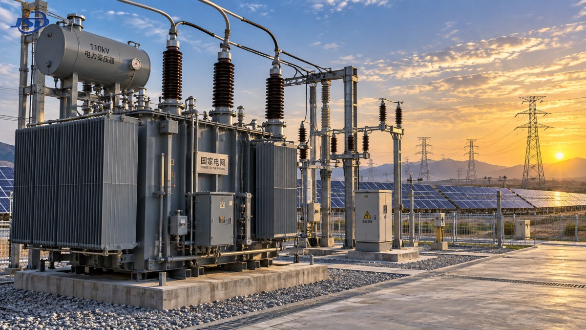
Oil cooling transfers winding heat through insulating liquid, tank surfaces, radiators, and, where fitted, forced-air equipment. ONAN cooling relies on natural oil circulation and natural air flow. ONAF adds fans to increase heat rejection. The choice should follow the required loading duty and site conditions rather than a preference for the highest available cooling class.
ONAN designs offer fewer auxiliary components and a simpler operating arrangement, but their usable loading margin is governed by radiator area, ambient temperature, oil circulation, and specified temperature rise. ONAF may support higher output within the same basic transformer envelope, yet it introduces fan controls, auxiliary power demand, wiring, alarms, and maintenance obligations. A forced-air rating should not be treated as continuously available unless the fan duty, control logic, redundancy arrangement, and loss of auxiliary supply have been considered.
Ambient temperature must be stated clearly in the procurement specification. High daytime temperature, direct solar exposure, restricted air circulation around radiators, and nearby heat-emitting equipment reduce cooling margin. At cold sites, oil viscosity and fan operation at low temperature require review, particularly after extended shutdowns. The equipment layout should preserve clear airflow paths around radiators and permit removal or servicing of fans without disturbing high-voltage connections.
Losses also need to be separated into no-load and load losses. No-load loss persists whenever the transformer is energized, including low-generation periods. Load loss rises with current and is especially relevant when the unit is expected to operate near rating. The lowest figure in one category does not necessarily produce the most suitable lifecycle result. The comparison must use the expected energization hours, loading profile, and cooling duty of the particular project.
Impedance, Short-Circuit Strength, and Harmonic Duty
Specified impedance controls voltage regulation and limits the fault current contributed through the transformer. Raising impedance can reduce downstream fault duty, but it also increases voltage drop under load and can complicate parallel operation. Selecting a standard impedance value without reviewing the fault study is a common source of later design changes, especially where switchgear interrupting ratings are close to calculated fault levels.
Short-circuit withstand must be evaluated against the actual network fault level and clearing time. The mechanical force on windings during a fault is strongly related to current magnitude, while thermal stress depends on both current and duration. Protection may clear a local fault quickly, but a backup-protection scenario can expose the transformer for longer. Winding bracing, conductor geometry, clamping, and lead support should be appropriate for the declared duty.
Nonlinear loads and converter-connected generation require a harmonic review. Harmonic current increases eddy-current losses in windings, leads, tank parts, and structural components. A transformer can meet its fundamental-frequency rating while experiencing higher localized heating under distorted current. The appropriate response depends on the harmonic spectrum, current magnitude, winding configuration, conductor design, and cooling margin. A generic statement that a transformer is “harmonic resistant” is not a substitute for a defined duty profile.
For outdoor solar collection systems, a Step-Up Transformer for Photovoltaic Power Stations may be specified with 500 kVA to 5000 kVA capacity, high-voltage options such as 10 kV, 20 kV, or 35 kV, and low-voltage options including 0.315 kV, 0.4 kV, and 0.69 kV. These values should still be checked against the inverter output, collection-cable voltage drop, required vector group, tap requirement, and harmonic loading rather than selected as an isolated package.
Outdoor Mechanical Details Affect Reliability and Site Work
Tank construction, corrosion protection, radiator mounting, and sealing arrangement should suit the climate and the expected service life between major outages. A coating system that performs adequately in a sheltered inland yard may require stronger preparation and protection in a marine or chemically contaminated location. Attention should extend to exposed fasteners, cabinet hinges, cable-box interfaces, radiator valves, and areas where water can collect.
The conservator, breather, pressure-relief device, oil level indicator, temperature instruments, and control cabinet must remain accessible after installation. A layout that leaves no safe route to inspect gauges or isolate a radiator turns routine observation into a shutdown task. Cable entry direction and phase spacing must also be coordinated with termination hardware, bending radii, surge arrester location, and safe clearances to grounded structures.
Fire and environmental planning are site-specific. Oil containment, drainage, separation from adjacent equipment, fire detection, and extinguishing arrangements must match the project design basis and local requirements. The oil volume alone does not define the hazard; transformer placement, enclosure geometry, drainage route, nearby cable trenches, and possible propagation paths determine whether a spill or fire event can remain localized.
Factory Evidence Should Match the Risks Being Controlled
A complete submittal package should make it possible to verify that the offered transformer matches the stated duty. Core loss and load loss values, impedance tolerance, temperature-rise data, insulation levels, tap positions, terminal arrangement, sound level where relevant, oil data, accessory list, outline drawing, foundation loads, and transport dimensions should be internally consistent. Discrepancies between the general arrangement drawing and the electrical data sheet are not cosmetic; they can affect cable design, civil work, protection settings, and commissioning.
Routine test records confirm essential electrical checks on the completed unit, but they should be read alongside the project requirements. Ratio and polarity testing, winding resistance measurements, insulation tests, impedance measurements, no-load and load-loss tests, and leak checks each address different failure modes. Where a special application requirement exists, such as elevated fault duty or unusual harmonic content, acceptance requirements should identify how that condition is demonstrated rather than assuming routine tests cover it.
Before shipment, confirm the oil handling condition, gas cushion or nitrogen preservation method where used, shipping braces, impact recording requirements, loose accessories, and documents needed for site assembly. Large outdoor transformers can arrive with radiators, bushings, conservators, or cable boxes removed for transport. The installation sequence must account for clean assembly conditions, oil filtration equipment, vacuum treatment where required, torque control, grounding connections, and post-assembly electrical testing.
Commissioning and Maintenance Start With the Specification
Long-term maintainability is largely set before the purchase order is issued. Instrumentation should support the operating philosophy: oil temperature indication, winding temperature simulation or monitoring where specified, pressure indication, liquid-level visibility, alarm contacts, and fan status must be meaningful to the protection and supervisory systems. Adding incompatible instruments after delivery often leads to extra wiring, unclear alarm logic, or inaccessible cable routes.
Oil sampling points should be reachable without removing guards or placing personnel near energized terminals. Baseline oil test results at commissioning provide a reference for later condition assessment. Subsequent interpretation should consider trends, loading history, temperature, moisture condition, and maintenance events. A single abnormal result may point to sampling error, external contamination, aging insulation, overheating, or a developing electrical defect; the correct response follows from corroborating evidence.
Selection is complete only when the transformer data, civil layout, protection design, cable schedule, surge protection, and commissioning plan describe the same installation. Resolving those interfaces before fabrication avoids the most expensive outdoor-project problems: unsuitable clearances, inaccessible equipment, incorrect voltage regulation, inadequate cooling space, and avoidable rework after delivery.

Get a Quote
Regardless of whether you require general advice or specific support, we are happy to help you.
Send Us Your Inquiry Today

Jinshida Electric remains committed to contributing to global energy development through professional manufacturing and superior service.