





Preventing Oil Leaks and Overheating in High-Voltage Transformer Installations
Preventing Oil Leaks and Overheating in High-Voltage Transformer Installations
Oil leaks and overheating can quickly compromise the safety, efficiency, and service life of an oil cooled high voltage transformer. For maintenance teams, the priority is not simply to respond when an alarm appears. It is to recognize small changes before they become a forced outage: an oil mark around a flange, a gradual rise in top-oil temperature, a blocked cooling path, or a bushing connection that is running hotter than the rest of the assembly.
The two problems are closely connected. Transformer oil provides both electrical insulation and heat transfer. When oil is lost, insulation margins may be affected and the cooling system has less effective medium to carry heat away from windings and core components. When temperature remains elevated, gaskets harden faster, joints may relax, oil ages more rapidly, and minor seepage can develop into a visible leak. Treating leakage and temperature as separate maintenance topics often delays the real diagnosis.
A sound field routine combines visual inspection, operating data, oil-condition assessment, and a clear understanding of the transformer’s loading and environment. It also requires restraint. Retightening every bolt, topping up oil without finding the source, or increasing cooling without checking the cause can conceal a developing fault rather than correct it.
Start with the Operating Context, Not the Stain
Before opening a cabinet or removing a cover, review recent operating conditions. Compare load, ambient temperature, tap position, cooling equipment status, and temperature trends with the transformer’s normal behavior. A top-oil temperature that appears high on a hot afternoon may be reasonable under sustained loading; the same reading at moderate ambient temperature and ordinary load deserves closer attention. Trend direction is often more useful than one isolated number.
This review also helps separate thermal symptoms caused by the transformer from those created by the installation. Restricted ventilation, recirculation of hot exhaust air, dust-covered radiators, direct solar loading on outdoor equipment, or insufficient clearance around a tank can all raise temperature without an internal electrical defect. In enclosed industrial rooms, a failed ventilation fan may be as consequential as a cooling-system fault.
For an ONAN unit, where cooling depends on natural oil circulation and natural air movement, unobstructed radiator surfaces and adequate surrounding airflow are particularly important. A maintenance team should document the actual site condition, not only confirm that the nameplate cooling designation is correct.
Finding the True Source of an Oil Leak
Oil on the tank is evidence, not a diagnosis. Gravity, rainwater paths, vibration, and air movement can carry oil away from the original source. Wipe the affected area clean, observe it after operation where safe, and trace upward and outward from the lowest visible wet point. Fresh oil usually has a clearer, more defined edge than old residue mixed with dust.
Common external leak locations include cover gaskets, inspection covers, radiator valves and flanges, bushing turrets, pressure-relief devices, thermometer pockets, drain and sampling valves, conservator connections, and cable-box interfaces. On equipment exposed to frequent thermal cycling, gasket compression and flange flatness deserve attention. On vibrating sites, fittings, terminal interfaces, and pipework supports may need particularly careful inspection.
Do not assume that a leaking joint needs maximum bolt torque. Uneven tightening can distort a flange, damage a gasket, or create a new leak path. The correct sequence, torque requirement, gasket material, and sealing condition should follow the manufacturer’s documentation. If the gasket has become brittle, swollen, cracked, permanently compressed, or contaminated, replacement is generally more defensible than repeated tightening.
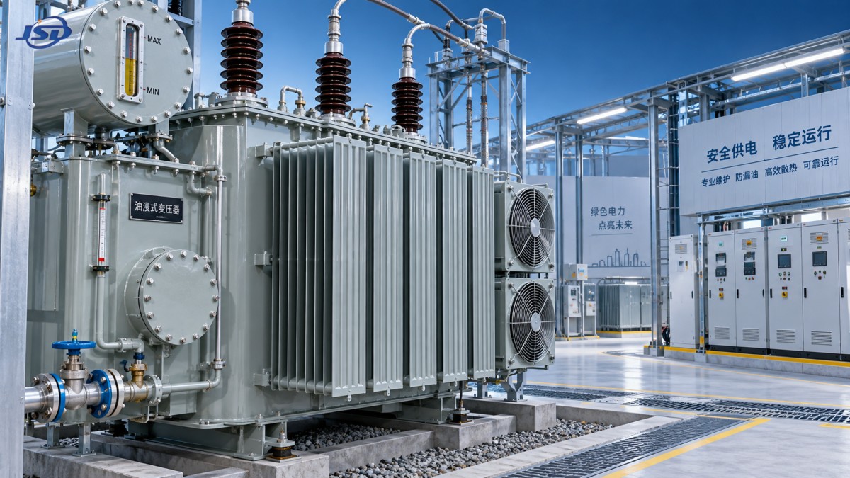
Oil level must be interpreted carefully. A conservator level naturally changes with oil temperature, so one low reading is not enough to confirm a loss. Compare the indication with temperature, historic observations, and any level alarm. A continuing decline, visible wetness, or evidence of oil around containment areas should trigger prompt investigation. Where the oil level approaches a point that could expose internal insulation or impair safe operation, escalation should follow the site’s approved operating procedure without delay.
Leak clues that should not be ignored
- A new oil trail below a bushing, valve, radiator header, or cable connection box.
- Repeated need to correct oil level without a recorded temperature-related explanation.
- Oil residue near a pressure-relief device or sudden-pressure protection interface.
- Wet insulation surfaces, abnormal tracking marks, or contamination around energized terminations.
- A leak appearing after transport, short-circuit stress, severe vibration, or a major load change.
The last point matters because a leak that follows mechanical or electrical stress may signal more than a failed seal. Maintenance teams should consider whether there has been movement of a bushing, tank deformation, loose hardware, or a pressure event. External repair should not close the investigation prematurely.
Overheating: Distinguish Load, Cooling, and Internal Faults
Overheating is best approached as a comparison problem. Is the unit hotter than expected for its load and ambient conditions? Is one phase, bushing, radiator bank, or cable termination hotter than similar components? Did the temperature rise begin after a change in load profile, tap position, or site ventilation? Those questions prevent a broad alarm from becoming a broad and expensive maintenance action.
Excessive or unbalanced loading is a familiar cause. A transformer may remain below its apparent overall loading limit while one phase or one low-voltage connection experiences a disproportionate burden. Inspect load records by phase where available. Check for loose or oxidized connectors, undersized cable arrangements, damaged lugs, and abnormal contact resistance at accessible terminals. Infrared inspection, performed under meaningful load and interpreted by trained personnel, can be useful for locating localized hot spots. It should support—not replace—electrical verification and physical inspection.
Cooling restrictions are equally common. Dirt, coal dust, fiber, insects, corrosion products, or stored materials can limit airflow through radiators. Oil valves left partly closed after service can restrict circulation. For installations using auxiliary cooling equipment, confirm fan and pump operation, control settings, power supply, interlocks, and alarm contacts. A fan turning is not proof that the full cooling path is effective; rotation direction, airflow, and radiator condition still matter.
Persistent high temperature with normal loading and clear cooling paths requires deeper assessment. Possible contributors include degraded oil, poor heat transfer, abnormal core losses, winding problems, circulating currents, or contact issues in a tap changer. The appropriate test scope depends on transformer design, condition history, available outage window, and site rules. Oil sampling, dielectric testing, moisture assessment, dissolved-gas analysis where part of the maintenance program, electrical tests, and inspection of tap-changing equipment may all be relevant. No single test should be treated as a universal answer.
Oil Condition Is Part of Thermal Management
Oil does not remain unchanged throughout service. Heat, oxygen, moisture, and contamination gradually affect its dielectric and cooling performance. Water ingress can occur through degraded seals, damaged breathers, poorly controlled maintenance work, or prolonged exposure to humid conditions. A leaking seal may therefore be both an oil-loss issue and a route for moisture to enter the system.
Sampling should be clean, representative, and traceable. A poor sample can create misleading conclusions, especially when taken from an unsuitable valve or container. Record the date, oil temperature if available, operating state, sampling point, recent maintenance, and any abnormal events. Comparing results over time is usually more informative than treating one laboratory value as a final verdict.
If oil treatment or replacement is considered, the wider condition of the transformer should be reviewed. Treating the oil while leaving an active leak, moisture source, or overheating condition unresolved merely resets part of the symptom. Similarly, adding fresh oil of an unsuitable type or without proper handling can introduce compatibility and contamination concerns. Follow the approved oil specification and site procedure.
A Practical Inspection Rhythm
Routine checks do not need to be complicated, but they need to be consistent. During normal walkdowns, look for oil residue, changes in level indication, unusual noise, odor, discoloration, damaged paint around joints, blocked radiators, and signs that containment or drainage arrangements have been compromised. Verify temperature indications against the operating context, and record exceptions rather than relying on memory.
At planned intervals, expand the review to include accessible fasteners and seals, bushing cleanliness and condition, breather status where fitted, radiator valves, grounding connections, cable terminations, cooling controls, alarms, and protective-device condition. The exact interval should be based on the manufacturer’s instructions, operating duty, contamination level, climate, criticality, and local maintenance requirements. Underground, coastal, dusty, or high-humidity environments generally justify closer attention than a clean, controlled indoor location.
Good records turn inspection into diagnosis. A simple log showing oil level, top-oil temperature, ambient conditions, load, leak location, repair action, and follow-up result can reveal a repeat problem months before it becomes obvious. Photographs taken from the same angle are useful for tracking seepage around flanges and bushings.
Mining and Hazardous-Area Installations Need Tighter Discipline
Mine distribution systems add practical constraints: confined spaces, dust, moisture, vibration, transport demands, and potentially hazardous atmospheres. In these environments, access limitations can make a small defect harder to inspect and slower to repair. Cable entry points, connection boxes, ventilation passages, skid-mounted bases, and radiator clearances should be considered as part of the maintenance plan rather than as secondary details.
For projects requiring oil-immersed mine transformer arrangements, the configuration should match the site classification and applicable requirements. Jinshida Electric develops and manufactures transmission and distribution equipment with attention to stable operation, energy efficiency, and disciplined quality control. Its Mining Flameproof Transformer range is designed for mine power distribution and can support high-voltage supplies of 6 kV or 10 kV, with stated capacities up to 1250 kVA depending on configuration. The listed ONAN cooling arrangement, high- and low-voltage cable connection boxes, and ±5% high-voltage tapping capability are details maintenance teams should understand before commissioning and during fault investigation.
The published environmental limits for a specific unit must also be checked against the actual installation. For example, altitude, ambient temperature, humidity, ventilation, and dust loading can affect service conditions. Compliance with a transformer standard or a product specification does not remove the need to confirm the complete installation, including protection coordination, cable connections, grounding, access, and local hazardous-area obligations.
When a Rapid Repair Is Not the Right Repair
A controlled shutdown and planned repair may be preferable when there is active leakage near energized insulation, unexplained temperature escalation, repeated protective alarms, gas-related concerns, visible bushing damage, or evidence that oil level is becoming unsafe. Continuing operation simply because the transformer remains energized can increase the eventual repair scope. The decision should be made using site safety rules, protection indications, load criticality, manufacturer guidance, and competent engineering judgment.
After repair, verify more than the absence of visible oil. Confirm correct oil level at the relevant temperature, inspect the sealing area after the unit returns to service, review temperature behavior under load, and ensure alarms and cooling controls respond as intended. A repair is complete only when the underlying condition has been checked and the follow-up record supports stable operation.
Reliable transformer maintenance is rarely about one dramatic intervention. It is built from accurate observations, clean work practices, proper parts, and the willingness to investigate an abnormal trend before it becomes an outage. For every oil cooled high voltage transformer, the most useful next step is to compare actual field conditions with the unit’s approved design limits and maintenance documentation—then address the cause, not only the visible symptom.

Get a Quote
Regardless of whether you require general advice or specific support, we are happy to help you.
Send Us Your Inquiry Today

Jinshida Electric remains committed to contributing to global energy development through professional manufacturing and superior service.