





Matching Distribution Transformers to Wind, Solar, and Battery Energy Projects
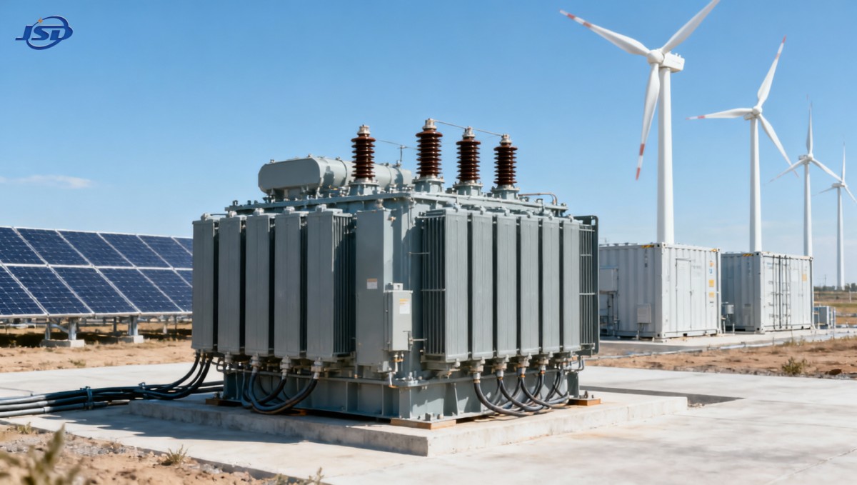
Selecting distribution transformers for a wind farm, solar plant, or battery energy storage system is not a matter of matching nameplate kVA to a single expected load. Renewable projects impose operating patterns that conventional distribution networks may not: intermittent export, reverse power flow, inverter-driven harmonics, rapid changes in loading, and long periods at low output followed by high-output peaks.
For project managers, the practical decision is to specify a transformer system that meets the interconnection point requirements while remaining stable through the project's real operating range. A transformer that is acceptable at nominal generation can still create losses, voltage-control problems, protection coordination issues, or delivery delays if its impedance, tap range, insulation level, cooling arrangement, and auxiliary interfaces were selected without reference to the plant design.
Distribution transformers for renewable energy projects should therefore be selected from the electrical architecture outward. Start with how power moves through the site, how the utility requires the project to behave, and what conditions will exist at the transformer terminals. The equipment choice follows from those answers.
Begin with the project electrical topology
Wind, solar, and battery projects can all use medium-voltage collection systems, but their transformer duties are different. Before comparing transformer quotations, map each voltage conversion point and identify whether the transformer serves generation, station service, a storage block, a temporary construction supply, or a grid-support function.
In a utility-scale solar plant, inverter stations commonly step low-voltage inverter output up to the collector voltage. The transformer experiences a generation-led profile: output rises and falls with irradiance, while inverter controls may influence power factor and reactive power flow. In a wind project, each turbine transformer or grouped transformer must accommodate the turbine's operating profile, cable arrangement, and site environmental exposure. Battery systems add a different complication: the same transformer may see import during charging and export during discharge, sometimes at high utilization in both directions.
These distinctions affect more than capacity. They influence vector group selection, impedance, tap requirements, thermal assumptions, metering placement, protection settings, and the need for interfaces with switchgear and plant controls.
- Generation step-up duty: Define the inverter or turbine output voltage, maximum continuous active power, reactive-power range, and planned operating power factor.
- Collector-system duty: Review feeder length, cable charging, voltage drop, fault level, and the number of generation blocks that can operate simultaneously.
- Battery bidirectional duty: Confirm charging and discharging power independently. Battery energy capacity does not define transformer capacity; the converter's AC power rating and dispatch strategy do.
- Station-service duty: Separate auxiliary loads from export transformers where practical. HVAC, controls, lighting, fire systems, communications, and battery containers may have a demand profile unrelated to generation.
A common early-stage error is to use the DC capacity of a solar project, the installed turbine nameplate total, or battery MWh rating as a shortcut for transformer sizing. Those figures describe the plant, but they do not by themselves establish the AC duty at a particular transformer. The correct basis is the maximum coincident apparent power at that installation point, including the required reactive-power operating range and any approved overload duty.
Size for apparent power, operating range, and temperature
Transformer rating is expressed in kVA or MVA because windings and cooling systems respond to current and losses, not only active MW. If a project must export active power while providing or absorbing reactive power, the apparent power can exceed the active-power value that appears in commercial project summaries.
For example, a solar inverter block intended to export near its maximum active output may have limited reactive margin at that point. Conversely, an interconnection agreement may require the plant to remain capable of reactive support across a defined power range. The transformer must be assessed against the resulting kVA, not against a simplified MW figure. The same review is important for battery systems that may be scheduled for high-power charging or discharge while participating in voltage regulation.
Ambient conditions also belong in the rating calculation. Outdoor transformers at a hot, enclosed, dusty, high-altitude, or poorly ventilated location may not achieve the same continuous loading as a unit installed under standard reference conditions. Solar sites can be especially misleading because the equipment may be exposed to high irradiance and reflected heat at the same time as the plant reaches peak output. Wind sites may instead be dominated by low temperatures, salt exposure, condensation, or strong wind-driven contamination.
Ask the supplier to state the rating basis clearly: ambient temperature assumptions, altitude, cooling mode, insulation system, permissible temperature rise, and whether the stated capacity is continuous or dependent on a loading cycle. A proposal that lists only voltage and kVA leaves project teams without enough information to compare thermal capability fairly.
Losses deserve separate attention. No-load losses continue whenever the transformer is energized, including hours when renewable output is low. Load losses increase with current and matter most when the plant runs near maximum throughput. The least-cost purchase option can be a poor lifecycle choice when a transformer stays energized continuously, serves a heavily dispatched battery asset, or is replicated across many inverter blocks. The evaluation should compare guaranteed losses on a like-for-like basis, with the project owner's assumed operating profile rather than a generic utilization estimate.
Voltage control and impedance must match the grid study
Voltage performance is often where a technically adequate transformer becomes a project problem. Renewable sites may be electrically remote from the point of interconnection, connected through long medium-voltage feeders, or exposed to a weak grid. Under those conditions, transformer impedance, tap position, vector group, and the control behavior of inverters or battery converters interact with the wider network.
Impedance should not be treated as a standard catalogue field. Higher impedance can help limit fault current, but it also produces greater voltage drop under load. Lower impedance can improve voltage regulation yet increase fault-duty exposure for downstream equipment. There is no universally correct percentage; it must align with the network model, switchgear interrupting ratings, protection study, cable characteristics, and utility requirements.
The tap arrangement deserves the same scrutiny. A de-energized tap changer may be suitable where the grid voltage is stable and seasonal adjustment is sufficient. Where the project needs regular voltage adjustment, the decision may point toward an on-load tap changer, voltage-regulation equipment elsewhere in the system, or tighter coordination with inverter controls. Selecting an on-load tap changer simply because generation is variable can add cost and maintenance without solving the actual control issue. Selecting a fixed arrangement without checking the expected voltage envelope can leave the operator with chronic curtailment or reactive-power constraints.
Project specifications should also state the required phase displacement and grounding arrangement. These choices affect protection, harmonic paths, zero-sequence behavior, and the connection of the collection system. They should be established by the electrical design and interconnection study before the transformer manufacturer finalizes winding configuration.
Account for inverter and battery power quality at the specification stage
Modern inverter-based resources do not create the same waveform conditions as a purely sinusoidal load. Harmonic currents, switching effects, control interactions, and non-linear auxiliary loads can increase transformer heating beyond what a simple fundamental-frequency load calculation suggests. The risk is project-specific: it depends on converter design, filtering, cable layout, point of measurement, grid strength, and the operating modes required by the grid operator.
The useful question for the transformer package is not whether harmonics exist, but what harmonic spectrum and distortion limits have been assumed. The electrical designer should provide relevant study outputs and require the transformer supplier to confirm the thermal design against that duty. Where harmonics are material, this may affect conductor sizing, stray-loss allowance, shielding, impedance selection, and temperature-rise margins.
Battery facilities require another check: frequent cycling may produce sustained high-current intervals in both directions. A transformer that sees one daily solar peak may have a different loss and thermal profile from one used to charge during low-price periods and discharge during evening peaks. The proposed dispatch profile does not need to predict every future market decision, but it should define credible maximum charge, discharge, and auxiliary-load cases.
Specify the physical installation as carefully as the electrical rating
Many renewable projects are built in locations where access, civil work, and environmental exposure drive installation risk. Transformer selection should consider transport route limits, lifting plans, foundation design, drainage, seismic or wind requirements where applicable, clearance for cable termination, and access for inspection or replacement. A unit that fits electrically but cannot be delivered on the intended route, or requires a larger pad than the civil package allowed, can disrupt the construction sequence.
Environmental protection should be stated in terms of the actual site conditions. Coastal and desert projects, mining-adjacent areas, agricultural locations, and exposed ridgelines may all need different measures for corrosion resistance, contamination, moisture control, enclosure protection, radiator exposure, or animal and vegetation management. Generic outdoor service language is insufficient where a transformer is expected to remain accessible and reliable for the full project life.
Construction power and commissioning are also easy to overlook. A renewable plant may need temporary medium- and low-voltage distribution well before permanent collector equipment is energized. For temporary engineering works, emergency restoration, or staged energization, a trailer- or skid-mounted package can reduce field assembly work by integrating transformer, switchgear, protection, and controls. A Mobile Temporary Compact Substation can be relevant where a 500 kVA to 1250 kVA temporary supply is needed at 10 kV through 35 kV on the high-voltage side and 0.4 kV on the low-voltage side. Its role should be defined as a temporary or contingency asset, not substituted for the permanent transformer design without checking the protection, grounding, fault-duty, and interconnection requirements.
Turn the transformer specification into a project control document
A concise but technically complete transformer schedule prevents many late-stage disputes. It should give manufacturers enough information to design correctly and give the owner a basis for comparing bids. The schedule should identify system voltages and frequency, rated capacity, cooling, vector group, impedance tolerance, tap range and tap-changer type, insulation and impulse withstand requirements, applicable standards, loss guarantees, terminal arrangements, monitoring requirements, environmental conditions, and required tests.
It should also identify interfaces. Confirm who supplies medium-voltage terminations, low-voltage bus or cable boxes, surge arresters, neutral grounding components, marshalling panels, temperature monitoring, oil level indication where relevant, remote alarm contacts, and communications interfaces. These details frequently fall between transformer, switchgear, SCADA, and EPC scopes when they are not assigned explicitly.
Factory testing and documentation should be aligned with the approved specification, not treated as a closing paperwork exercise. Review drawings early enough to catch terminal orientation, dimensions, weights, cable entry, tap settings, and accessory locations before fabrication. For larger or repeated transformer packages, a defined inspection and test plan gives the project team clear hold points without creating unnecessary delay.
Make the final choice against the operating model, not the nameplate alone
The best transformer choice for a renewable project is usually the one that fits a specific combination of grid conditions, converter behavior, site environment, construction constraints, and expected operating profile. Wind, solar, and battery assets may share distribution equipment, but their electrical duty should not be assumed to be identical.
Before releasing the order, project managers should be able to trace each major transformer parameter back to an approved design input: the interconnection requirement, the load-flow and fault study, the generation or storage operating envelope, the environmental design basis, or the construction plan. That discipline keeps distribution transformers from becoming a late-stage procurement item and makes them what they need to be: dependable infrastructure for moving renewable power from equipment in the field to the grid.

Get a Quote
Regardless of whether you require general advice or specific support, we are happy to help you.
Send Us Your Inquiry Today

Jinshida Electric remains committed to contributing to global energy development through professional manufacturing and superior service.