





Grid-Code Requirements for Distribution Transformers in Renewable Energy Projects
Grid-Code Requirements for Distribution Transformers in Renewable Energy Projects
Grid-code compliance is a critical requirement when selecting distribution transformers for renewable energy projects. Technical evaluators must assess voltage regulation, fault ride-through capability, harmonic performance, efficiency, insulation design, and monitoring compatibility.
The correct transformer is not simply the unit with an acceptable voltage ratio and capacity rating. It is an integration component that affects availability, protection coordination, losses, safety, and future grid compliance.
Start With the Grid Connection Study, Not the Transformer Datasheet
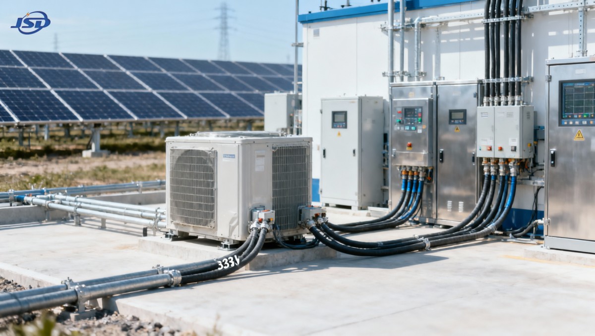
For distribution transformers for renewable energy projects, the grid connection agreement should be the primary design input. It defines operational limits that generic transformer specifications cannot fully address.
Technical evaluators should obtain the latest utility grid code, point-of-connection study, short-circuit report, protection philosophy, and reactive-power requirements before comparing transformer quotations.
These documents clarify voltage ranges, permissible voltage steps, frequency limits, fault levels, grounding requirements, power-quality thresholds, and the required behavior during abnormal network conditions.
A transformer that complies with IEC manufacturing standards may still be unsuitable if its impedance, tap arrangement, vector group, or insulation level conflicts with local utility requirements.
Renewable projects also require consideration of changing generation profiles. Solar output can rise rapidly, wind output can vary continuously, and battery systems can reverse power flow repeatedly.
Therefore, the evaluation should consider the entire electrical system: inverter output, collector cables, transformer impedance, switchgear ratings, relay settings, metering accuracy, and utility operating procedures.
The most important early decision is identifying whether the transformer serves a low-voltage inverter block, a medium-voltage collection network, auxiliary loads, or a dedicated storage conversion system.
Voltage Regulation and Tap Selection Must Match Renewable Operating Conditions
Voltage control is often the most visible grid-code issue in renewable installations. Generation export raises feeder voltage, especially when projects connect to electrically weak or remote distribution networks.
Evaluators should examine the permitted point-of-connection voltage range under minimum load, maximum generation, contingency operation, and expected future expansion of nearby renewable capacity.
Transformer turns ratio and tap positions must support the required operating range without forcing inverters to remain at reactive-power limits during normal production periods.
Off-circuit tap changers are common where the project has a stable design voltage. Their selected position should be based on modeled operating conditions, not only nominal nameplate voltage.
On-load tap changers may be justified for larger or variable networks, but they introduce additional capital cost, control logic, maintenance requirements, and coordination work with inverter Volt-VAR functions.
Tap range should also accommodate utility voltage changes. A project designed around one feeder voltage may later face altered network settings, higher generation density, or changed substation transformer ratios.
Technical teams should request a voltage-drop and voltage-rise calculation covering cable impedance, transformer impedance, inverter reactive-power output, power factor, and realistic generation dispatch scenarios.
For a 33 kV to 0.4 kV application, the selected ratio, tap range, and connection configuration should support both steady export and acceptable low-voltage bus conditions.
Impedance and Short-Circuit Performance Need System-Level Coordination
Transformer impedance is not a minor catalog value. It directly affects fault current, voltage regulation, inrush behavior, inverter protection coordination, and the transfer of harmonic currents through the network.
Low impedance can improve voltage regulation but may increase prospective fault current beyond switchgear interrupting capability. High impedance can limit faults but worsen voltage variation during changing generation.
The required impedance should be confirmed against the utility short-circuit study and the project protection coordination study. It should never be selected solely from standard product ranges.
Inverter-based resources normally contribute limited and controlled fault current. However, transformer impedance still influences the voltage seen by protection relays and the performance of anti-islanding functions.
Evaluators should verify thermal short-circuit withstand, dynamic mechanical withstand, and the calculated fault duty at all relevant buses. These checks should include utility-source and project-source contributions.
Neutral grounding deserves equal attention. The vector group and earthing transformer arrangement determine how earth faults are detected, limited, and cleared within collector systems and low-voltage auxiliary networks.
A delta winding can block zero-sequence current between sides, while a grounded-wye winding can provide a fault-current path. The preferred arrangement depends on the project grounding study.
Documented impedance tolerances are important where parallel transformers are planned. Excessive variation can create unequal loading, circulating currents, and unexpected protection behavior during normal operation.
Fault Ride-Through Is Primarily an Inverter Requirement, But Transformers Still Matter
Fault ride-through requirements generally apply to generation equipment, particularly inverters and plant controllers. Nevertheless, transformer design strongly influences the voltage conditions those devices experience during network faults.
During a voltage dip, transformer impedance, vector group, grounding, saturation characteristics, and protection response can affect the residual voltage supplied to inverter terminals and auxiliary equipment.
Technical evaluators should review fault simulations for symmetrical faults, single-line-to-ground faults, phase-to-phase faults, and cleared-fault recovery conditions at the point of common coupling.
The transformer should not create avoidable disconnection risks through inappropriate protective settings, excessive voltage displacement, inadequate insulation coordination, or nuisance operation of temperature and gas-alarm systems.
For renewable plants with battery storage, bidirectional power flow adds another operating mode. The transformer must tolerate charging and discharging duty without unacceptable voltage deviation or thermal stress.
Protection settings should distinguish between internal transformer faults and external grid disturbances. Overly sensitive protection can trip a healthy transformer when grid codes expect the plant to remain connected.
Coordination between transformer protection, feeder relays, inverter controls, and the plant controller should be demonstrated through time-current curves, fault studies, and commissioning test procedures.
Harmonic Performance Requires Attention to Winding Design and System Resonance
Modern solar, wind, and storage systems use power electronic converters that can introduce harmonic and interharmonic currents. Transformer selection must support the project power-quality strategy, not merely basic load transfer.
Although inverter filters reduce emissions, background distortion and network resonance can still create elevated thermal stress. Harmonics increase eddy-current losses and may raise winding hot-spot temperatures.
Evaluators should request harmonic studies that consider inverter switching characteristics, cable capacitance, capacitor banks, filter stages, grid impedance, and likely operating configurations across the plant lifecycle.
The study should identify voltage distortion at the point of connection and current distortion at transformer terminals. It should also assess resonance frequencies that may amplify otherwise moderate harmonic components.
Winding construction, conductor geometry, shielding arrangements, and transformer impedance influence harmonic losses. Manufacturers should state any harmonic derating assumptions rather than relying on generic capacity declarations.
Delta-connected windings can provide a circulating path for certain triplen harmonic currents, helping prevent their transfer into upstream networks. However, this behavior must align with grounding and protection objectives.
Where harmonic exposure is significant, specify temperature-rise limits, harmonic loss evaluation, insulation thermal class, and acceptable loading conditions under the actual harmonic spectrum expected at site.
Power-quality acceptance testing should be defined early. Clear requirements for metering locations, aggregation intervals, operating states, and compliance responsibility reduce disputes after commercial operation begins.
Efficiency and Thermal Design Affect Lifetime Energy Yield
Transformer losses are continuous project costs. Even when generation is variable, no-load losses remain energized whenever the transformer is connected, while load losses rise with current and temperature.
Technical evaluators should compare total ownership cost rather than purchase price alone. A lower-loss transformer can produce meaningful lifetime savings in high-utilization renewable and storage projects.
The comparison should use realistic energy profiles, ambient temperature, expected loading, tariff assumptions, curtailment risk, and the financial value assigned to losses during peak generation periods.
Thermal design must account for local climate and installation conditions. High ambient temperatures, enclosed substations, dust, altitude, and restricted airflow can reduce usable loading capacity substantially.
Dry-type transformers require particular attention to ventilation paths and enclosure design. Air circulation must be sufficient to prevent sustained hot spots during high generation or forced cooling operation.
Thermal margins should not be consumed by optimistic assumptions. Renewable developers often expand capacity, alter dispatch strategies, or add energy storage after initial commissioning, increasing transformer duty.
A transformer rated for 120 percent load under forced-air cooling may support operational flexibility, but the controls, sensors, fans, ventilation, and maintenance plan must support that duty.
Loss values should be verified against the applicable test standard and guaranteed at stated reference temperatures. Technical bidders should clearly distinguish between guaranteed figures and typical values.
Insulation, Fire Safety, and Environmental Conditions Can Decide the Technology Choice
The site environment often determines whether oil-filled or dry-type equipment is more appropriate. Indoor substations, rooftops, data centers, tunnels, and sensitive industrial locations may require enhanced fire performance.
Cast-resin dry-type transformers avoid oil leakage risk and can offer strong fire behavior, making them relevant where containment systems, fire separation, or environmental restrictions complicate liquid-filled installations.
For example, the 33kV Cast Resin Dry-Type Distribution Transformer is designed for renewable energy systems requiring 33 kV input and 0.4 kV output distribution.
Its listed capacity range spans 30 to 2500 kVA, while the broader specification list reaches 3150 kVA. Final selection should still follow project load-flow and thermal studies.
Insulation evaluation should consider system voltage, lightning impulse withstand, switching transients, cable length, surge arresters, and the possibility of repeated inverter-generated voltage stress.
A stated lightning impulse withstand level of 175 kV can be relevant for medium-voltage applications, but insulation coordination must confirm whether it matches the local overvoltage environment.
Fire classification should be checked against project requirements, insurer expectations, building codes, and utility rules. An F1-class dry-type design can be valuable in locations with strict fire safety constraints.
Environmental requirements should also cover humidity, condensation, salt contamination, pollution level, seismic exposure, altitude, corrosion protection, and minimum and maximum ambient temperatures.
Monitoring Compatibility Should Be Specified as Part of Grid Compliance
Grid codes increasingly require renewable plants to provide operational data, event records, and remote control capability. Transformer monitoring should support the plant’s supervisory and maintenance strategy.
At minimum, evaluators should define winding temperature monitoring, alarm contacts, trip contacts, fan status, enclosure temperature, and communication interfaces required by the project control architecture.
For critical sites, additional monitoring may include partial discharge, vibration, humidity, load current, thermal imaging points, and power-quality data. The value depends on duty and access constraints.
Communication protocols must be compatible with the plant SCADA system. Specify protocol requirements, signal lists, time synchronization expectations, cybersecurity boundaries, and ownership of remote-access functions.
Temperature protection should coordinate with inverter curtailment and staged cooling where possible. Controlled output reduction may avoid unnecessary transformer trips while preserving compliance and equipment life.
Commissioning documentation should include factory test reports, routine test results, site acceptance tests, relay settings, communication checks, and evidence that alarms reach the intended control platform.
Monitoring data is also useful for validating design assumptions. Actual temperature, loading, voltage, and harmonic trends can reveal whether the transformer is operating within expected margins after energization.
A Practical Technical Evaluation Checklist
Technical evaluators can reduce procurement risk by converting grid-code requirements into a traceable transformer compliance schedule. Each requirement should identify evidence, responsibility, assumptions, and acceptance criteria.
First, confirm rated voltage, frequency, insulation level, tap range, vector group, impedance, neutral arrangement, and short-circuit withstand against the approved single-line diagram and grid studies.
Second, evaluate voltage regulation under maximum export, minimum export, charging mode, discharging mode, and contingency cases. Include inverter reactive-power capability and feeder voltage conditions.
Third, confirm thermal capacity using ambient conditions, enclosure ventilation, harmonic derating, expected overloads, and future expansion. Review both normal operation and credible abnormal operating periods.
Fourth, verify losses, efficiency guarantees, test methods, and economic assumptions. No-load loss is especially important where transformers remain energized during low-generation hours or seasonal downtime.
Fifth, assess protection, monitoring, communication, and maintainability. The transformer must work with the project’s relays, SCADA platform, access limitations, spare-parts strategy, and planned inspection intervals.
Finally, require clear factory and site test documentation. Compliance claims should be supported by type-test evidence, routine-test certificates, quality-system records, and project-specific engineering calculations where necessary.
Conclusion: Select for the Grid, the Site, and the Operating Envelope
Distribution transformers for renewable energy projects should be evaluated as grid-integration assets rather than standalone electrical components. Their design affects voltage stability, protection performance, power quality, safety, and lifecycle cost.
The strongest procurement decisions begin with the grid connection requirements and verify every major transformer parameter against actual system studies. Nameplate compliance alone is not sufficient for renewable applications.
Technical evaluators should prioritize voltage-control capability, impedance coordination, fault behavior, harmonic thermal performance, insulation suitability, efficiency, and monitoring integration before comparing commercial offers.
When these factors are documented in a project-specific compliance schedule, transformer selection becomes more defensible, commissioning risks decrease, and the renewable plant is better prepared for changing grid requirements.
Hot News
- 00
0000-00
How U.S. DOE efficiency rules affect distribution transformer manufacturers - 00
0000-00
How american type pad mounted transformer seismic qualification affects installation in California utility grids? - 00
0000-00
Do european compact substation transformer EMC compliance tests include conducted emissions up to 30MHz?
0000-00
Contact Us

Get a Quote
Regardless of whether you require general advice or specific support, we are happy to help you.
Send Us Your Inquiry Today

Jinshida Electric remains committed to contributing to global energy development through professional manufacturing and superior service.