





Key Electrical and Environmental Ratings for Wind Turbine Transformers
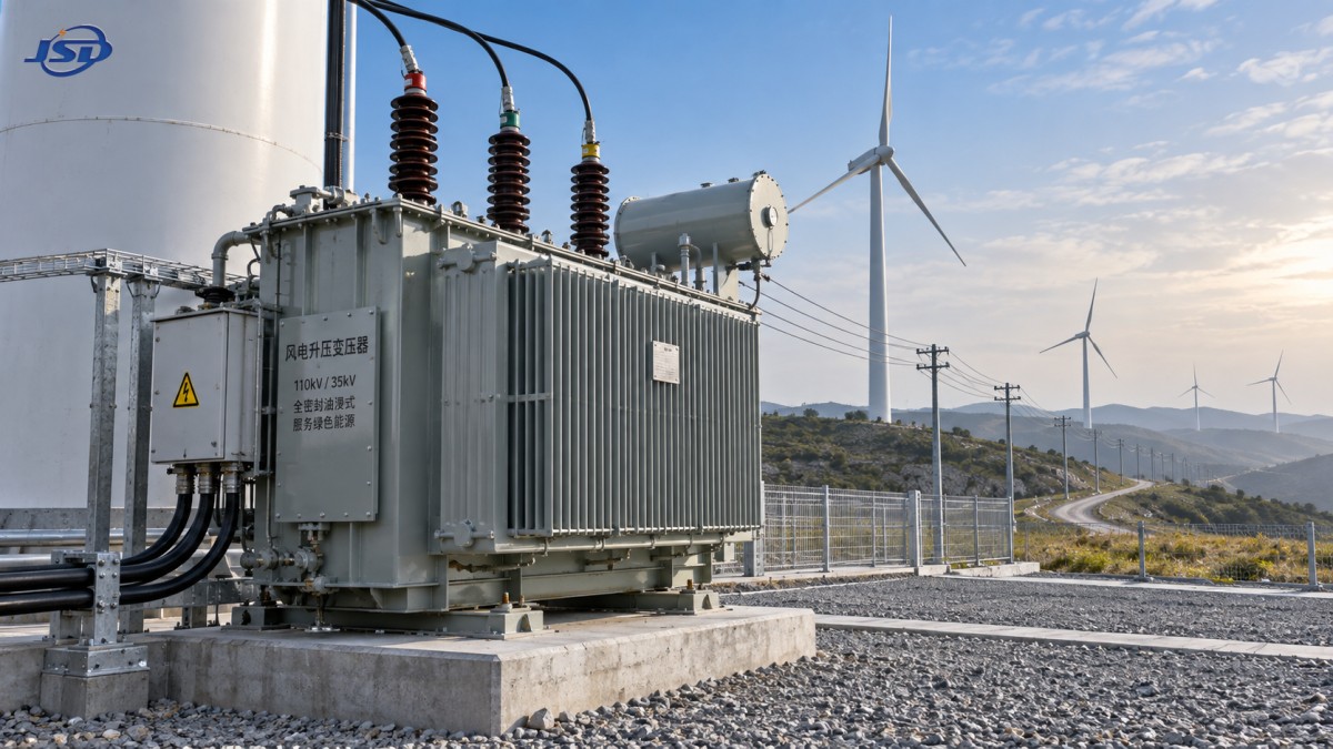
A high voltage transformer for wind turbines should be specified against the electrical stress and site exposure it will actually experience, rather than against nominal voltage and rated kVA alone. A turbine transformer sees variable generation, repeated thermal cycling, switching events, harmonics from power-electronic equipment, restricted maintenance access, and, in many locations, salt, moisture, dust, or low ambient temperatures. Ratings must describe the complete operating envelope: continuous duty, temporary overvoltage, insulation withstand, cooling margin, enclosure integrity, and the mechanical condition of the installation.
For a grid-connected turbine, a technically acceptable rating set also has to align with the collector system, cable network, grounding arrangement, protection settings, and the utility connection requirements. A mismatch in any one of these interfaces can leave a transformer correctly sized on paper while still exposed to insulation stress, overheating, nuisance trips, or accelerated corrosion.
Rated Voltage Must Be Read with the System Voltage Range
The rated high-voltage and low-voltage values establish the transformer ratio, but they do not fully describe voltage duty. The specification should state the nominal system voltage, the permitted operating range, frequency, and whether the transformer will be energized from a collector circuit with frequent voltage changes. Wind farm collector feeders may operate near the upper end of their voltage band for extended periods, particularly where reactive-power control and cable charging affect local voltage.
Tap range and tap position are therefore functional ratings, not secondary details. A transformer with a suitable fixed ratio can still produce an unsuitable low-voltage bus condition if the expected grid voltage differs from the assumed nominal value. Confirm whether off-circuit taps or on-load tap changing are required, how the selected tap is marked, and which tap is used for routine test values. The declared impedance, loss values, and voltage ratio should be tied to a stated principal tap.
Frequency requires equal attention. Core flux rises when voltage is applied at a lower frequency than the design basis, so a transformer intended for a 50 Hz system cannot be treated as automatically interchangeable with a 60 Hz application at the same voltage. Where commissioning tests use temporary power sources, their voltage-frequency relationship must remain within the transformer’s allowable limits.
Insulation Ratings: Separate the Different Withstand Duties
Insulation coordination is often weakened when a specification lists only a voltage class. The transformer must withstand several distinct stresses, each with a different origin and test purpose:
- Power-frequency withstand voltage addresses insulation performance under short-duration alternating-voltage stress and is relevant to internal clearances, winding insulation, bushings, and connected cable terminations.
- Lightning impulse withstand voltage addresses steep-front surges that can arrive from overhead connections, exposed switchgear, or lightning activity around the turbine and collector network.
- Switching and temporary overvoltage duty requires attention where vacuum switching, cable energization, capacitor banks, or grounding faults create stresses that are lower in front steepness but longer in duration.
These values must correspond to the actual highest system voltage and insulation coordination of the installation. Raising the nominal transformer voltage class without reviewing surge arresters, cable accessories, separable connectors, and clearances does not resolve a coordination problem. Conversely, a high impulse rating can be undermined by an incorrectly selected or poorly grounded arrester placed too far from the protected terminal.
Bushing selection needs the same discipline. Creepage distance, pollution performance, mechanical loading, connector arrangement, and enclosure penetration are separate considerations from the bushing voltage rating. In a coastal site, conductive salt deposits can turn an apparently dry external surface into a leakage path. In a tower-base installation, confined cable routing may place side loads or vibration loads on terminations that were not allowed for in the design.
Short-Circuit Withstand Is an Electromechanical Requirement
Transformer impedance affects fault current, voltage regulation, and coordination with upstream and downstream protective devices. It should not be selected simply by choosing a familiar percentage value. Lower impedance can improve voltage support but increases available fault current. Higher impedance reduces fault duty but can cause unacceptable voltage drop during turbine auxiliaries, converter operation, or inrush recovery.
The transformer must also withstand the thermal and mechanical effects of the prospective short-circuit current for the applicable clearing time. The electrical force on windings rises sharply with current. Repeated through-faults, even when protection clears correctly, can loosen winding clamping, shift conductors, or damage leads. A post-fault insulation test may still pass while mechanical displacement has reduced the margin against a later event.
Fault-duty review should include the contribution of the grid, parallel feeders, capacitor banks where relevant, and the actual clearing behavior of relays and breakers. Protective-device nameplate interrupting capability does not by itself prove that the transformer has adequate short-circuit withstand capability. The required evidence is a coordinated statement of available fault current, clearing duration, transformer impedance, and verified withstand design.
Thermal Ratings Need Ambient and Cooling Conditions
Rated capacity is valid only under its declared cooling method and reference ambient conditions. Outdoor wind turbine transformers can face direct solar loading, low natural ventilation, air recirculation inside a compact enclosure, blocked radiators, and wide seasonal temperature changes. An oil-immersed unit using ONAN cooling relies on unobstructed air movement around radiators; a nominal outdoor location does not guarantee adequate heat rejection when installed close to walls, cable trenches, or other equipment.
Temperature-rise limits should be reviewed alongside insulation thermal class, winding hot-spot allowance, oil temperature indication, and alarm or trip settings. A low average oil temperature does not necessarily prove that winding hot spots are controlled during fluctuating loading. Wind generation can change rapidly, and repeated load ramps create a thermal pattern different from a steady industrial load.
Cooling performance also depends on maintenance condition. Fins contaminated by dust, salt deposits, vegetation, or oily residue lose heat-transfer effectiveness. Radiator valves left partially closed after transport or service create a fault that may not be obvious during a brief no-load inspection. The acceptance documentation should identify the cooling arrangement, fan or pump duty where fitted, temperature sensor locations, and the logic linking alarms to turbine or feeder protection.
Losses, Harmonics, and the Meaning of Continuous Duty
No-load loss is present whenever the transformer is energized, making it relevant in wind applications that remain connected during low-generation periods. Load loss varies with current and rises further when harmonic current increases effective conductor loss and stray losses in windings, clamps, tank walls, and leads. A loss schedule quoted only at sinusoidal rated current is incomplete where converter equipment produces material harmonic content.
Harmonic assessment should identify the expected current spectrum, loading profile, and whether the transformer design has been evaluated for additional eddy-current heating. Harmonics are not interchangeable with simple kVA loading. Two units with the same RMS current can experience different local heating if their harmonic content differs. Neutral loading and zero-sequence behavior also matter when the winding connection and auxiliary loads permit triplen harmonic currents to circulate.
Core material selection influences no-load loss and sound behavior, but it does not remove the need to verify insulation, thermal, and environmental ratings. For renewable distribution duties within its stated range, an SBH15 Amorphous Alloy Transformer illustrates the distinction: an amorphous alloy core is associated with reduced no-load loss, while the installed unit still needs appropriate voltage, vector group, tap, cooling, outdoor protection, and short-circuit characteristics for the wind-farm circuit.
Vector Group and Grounding Affect Protection Behavior
The vector group establishes phase displacement and determines how zero-sequence currents and certain harmonics are transferred or contained. It must match the collector-system grounding philosophy and the protection scheme, especially where several turbine transformers operate in parallel or feed a common medium-voltage bus. A connection that appears equivalent for voltage transformation can behave very differently during an earth fault.
Review the neutral arrangement at both sides of the transformer. Confirm whether a neutral is brought out, solidly grounded, impedance grounded, or isolated by the winding configuration. Earth-fault relay settings, cable-screen bonding, surge protection, and touch-voltage controls depend on this arrangement. The transformer drawing should clearly show terminal designations, vector notation, neutral availability, and the intended grounding connection. Ambiguous terminal labeling becomes particularly hazardous during replacement work or phased expansion.
Outdoor Protection Is a System of Ratings, Not a Paint Specification
Environmental suitability begins with enclosure and ingress protection, but it extends to every exposed interface. The required protection level depends on whether the unit is installed in a nacelle, tower base, pad-mounted kiosk, compact substation, or open outdoor position. A sealed enclosure that restricts water ingress may also retain heat or condensation if drainage, breathing, and ventilation are not properly arranged.
For oil-filled transformers, tank sealing, pressure-relief equipment, liquid-level indication, corrosion protection, gasket compatibility, and cable-entry design should be evaluated together. Temperature swings can draw moist air into inadequately protected breathing systems. Water entering through a damaged gland or poorly sealed inspection cover may first affect control wiring and terminal insulation before it produces visible oil contamination.
Salt-laden air requires special attention to external insulation surfaces, fasteners, radiator coatings, marshalling boxes, and earthing connections. Inland dust creates a different pattern: it can accumulate on cooling surfaces and inside ventilated compartments, while fine conductive dust can compromise terminal clearances. In cold regions, the minimum ambient rating must account for oil viscosity, gasket behavior, instrument response, and the ability of protective mechanisms to operate without binding.
Mechanical Conditions Often Appear After Installation
Transport and installation conditions can invalidate otherwise sound ratings. Shock recorders, lifting instructions, center-of-gravity markings, and torque requirements should be part of the delivery documentation for larger units. Bushings, radiators, conservators, and cable boxes may be shipped separately; final assembly must preserve clearances, gasket compression, and oil-tight joints.
Vibration deserves particular review in turbine environments. Transformer vibration can originate from core magnetostriction, but vibration transmitted from nearby equipment, structural resonance, or loose mounting hardware has a different cause and requires a different corrective action. Low noise does not prove secure mechanical support. Verify base fastening, flexible connections where needed, cable support, and that no rigid conduit transfers excessive movement to bushings or control cabinets.
Evidence That Supports Acceptance
A useful acceptance package links nameplate ratings to traceable test and design information. It should identify the serial number, voltage ratio and tap range, vector group, rated power under the declared cooling mode, impedance, insulation levels, terminal arrangement, total mass and liquid volume where applicable, and environmental provisions. Routine test records should be consistent with the actual ordered configuration rather than a generic family document.
Before energization, confirm phase relationship, tap position, grounding continuity, insulation condition, winding resistance balance, protective-device wiring, oil condition where applicable, and torque of accessible electrical joints. Values should be compared with factory records and corrected for temperature when the test method requires it. A discrepancy is more useful when recorded with the test conditions than when reduced to a simple pass or fail statement.
The final rating decision is strongest when electrical limits and site exposure are reviewed as one set of conditions. Voltage class, impulse withstand, impedance, thermal performance, enclosure protection, corrosion resistance, and installation geometry all describe the same operating reality: sustained, safe transformation under a variable wind-generation duty cycle.

Get a Quote
Regardless of whether you require general advice or specific support, we are happy to help you.
Send Us Your Inquiry Today

Jinshida Electric remains committed to contributing to global energy development through professional manufacturing and superior service.