





Transformer Design Priorities for Wind Turbines in Harsh Offshore Conditions
Offshore Conditions Change the Transformer Design Brief
For an offshore wind project, transformer selection is an availability decision long before it becomes a catalog comparison. A transformer can meet its nameplate voltage, loss, and impedance requirements yet still become a recurring source of downtime if its enclosure, insulation system, cooling arrangement, connections, or monitoring were conceived for a sheltered onshore installation.
The first design priority is therefore to define where the transformer will live and what it will experience over its service life. A unit inside a turbine nacelle, in a transition piece, on an offshore substation, or in an enclosed auxiliary room faces different combinations of salt-laden air, condensation, motion, restricted airflow, vibration, and access constraints. Treating all of these locations as simply “marine environment” can lead to an under-specified design.
A high voltage transformer for wind turbines should be evaluated as part of the electrical and mechanical operating system. Its thermal duty depends on generation patterns and reactive-power requirements; its insulation duty depends on the cable network and switching arrangement; and its maintainability depends on whether a technician can safely reach it during a limited weather window. The most successful specifications turn those site realities into clear, testable design requirements before procurement begins.
Start With the Failure Environment, Not the Electrical Rating
Salt spray and high humidity are often grouped together, but they create different risks. Salt deposits can lower surface insulation resistance and accelerate corrosion at exposed metal interfaces. Humidity creates a separate condensation risk whenever equipment temperature falls below the local dew point. A transformer located in an enclosed compartment may avoid direct spray while still suffering repeated moisture cycles because ventilation is inadequate or the compartment cools during shutdown.
Project teams should ask the supplier to address the complete moisture path: enclosure seams, cable entry points, terminal compartments, breather arrangements where applicable, drainage, heater provisions, ventilation openings, and the materials used around bolted connections. A high enclosure protection rating alone is not a complete answer. An enclosure that excludes water but traps heat can create a thermal problem; one with generous ventilation may improve cooling but admit contaminants unless the airflow path is controlled.
Corrosion protection also needs to extend beyond the main tank or housing. Cable glands, terminal pads, fasteners, hinges, earthing points, radiator supports, cooling-fan guards, sensor fittings, and lifting points all need a coating or material strategy suited to the intended exposure. Small external parts are frequently where corrosion first compromises maintainability. A terminal enclosure that cannot be opened safely after several seasons is an operational defect even if the windings remain electrically sound.
For indoor transformer rooms on offshore platforms or substations, environmental control should be specified at room level as well as transformer level. Dehumidification, controlled ventilation, drainage, fire separation, access paths, and heat rejection influence the equipment selection. Placing a standard indoor transformer in a poorly managed room and relying on periodic inspection is a weak arrangement where access depends on vessel availability and weather.
Insulation Must Be Matched to Offshore Electrical Duty
Voltage class alone does not define insulation stress. Offshore collection systems combine long cable runs, switching operations, turbine converter behavior, transformer energization, and grid-side disturbances. The resulting transient environment should be considered alongside the basic insulation level required by the project’s electrical design. Coordination among transformer insulation, cable accessories, surge arresters, switchgear, and grounding is more useful than specifying each item in isolation.
For project leaders, the practical question is whether the supplier has been given enough system information to design and validate the insulation arrangement. This normally includes the network voltage and frequency, grounding method, cable lengths and construction, switching devices, expected operating configurations, transformer vector group, tap requirements, and the proposed surge-protection philosophy. Without this context, an insulation proposal may be technically compliant on paper while leaving avoidable exposure at terminals or windings.
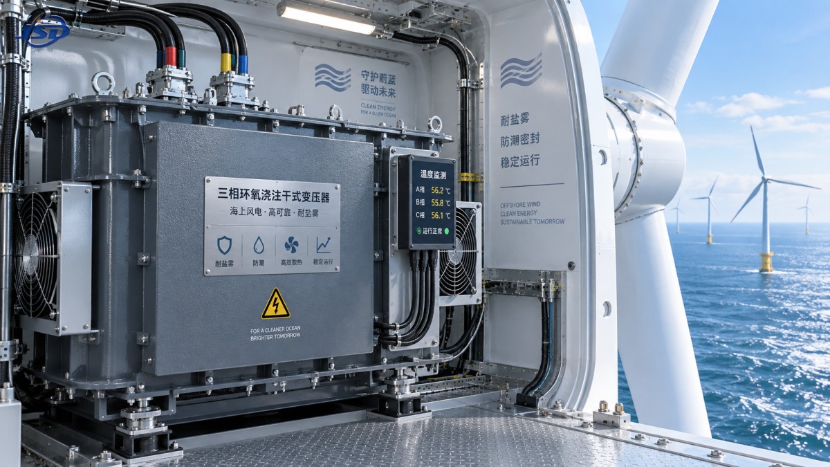
Cast-resin dry-type designs can be attractive for enclosed offshore applications where fire behavior, spill containment, and compact installation are important. Their suitability still depends on the local environment. The resin system, winding construction, partial-discharge performance, ventilation path, and surface cleanliness all matter. Dry-type equipment should not be assumed to be immune to condensation or salt contamination simply because it contains no insulating oil.
Where a 35 kV-to-low-voltage transformer is being considered for protected auxiliary distribution, such as controls, services, or balance-of-plant loads, a design with epoxy-resin insulation and temperature supervision may be appropriate. For example, the 35kV Three-Phase Cast Resin Dry-Type Distribution Transformer is available in 30-2500 kVA ratings, with 35 kV input, 0.4 kV output, and a stated 175 kV lightning impulse withstand level for its 35 kV configuration. Those figures are useful starting points, but they do not replace project-specific confirmation of insulation coordination, installation environment, and auxiliary load profile.
Thermal Margin Is an Availability Requirement
Offshore transformer cooling is rarely as simple as checking the site’s annual ambient temperature. Restricted compartments, salt-contaminated air paths, reduced fan effectiveness, nearby heat sources, solar loading on external housings, and blocked ventilation routes can all increase the actual operating temperature. For transformers installed in turbine structures, heat from converters and other electrical equipment can further change the compartment duty.
The useful design question is not whether the transformer can carry its nominal rating under nominal ambient conditions. It is whether it can maintain insulation life and stable operating temperature during the combinations that the project expects: high generation, elevated compartment temperature, reactive-power duty, reduced ventilation, and temporary loss of an auxiliary cooling component. A thermal model or duty assessment should use the installation’s real airflow conditions rather than a generic room assumption.
Forced-air cooling can provide operational headroom, but it also introduces components that require inspection and replacement. Fans, filters, drives, and control circuits need a maintenance strategy, including alarms that distinguish a fan fault from a temperature sensor issue. For a transformer designed to operate above rated load with forced-air cooling, the project should define how long that mode is permitted, what redundancy is present, and what action follows a cooling-system alarm.
Temperature monitoring should support decisions rather than merely collect values. Winding-temperature indicators, sensors, ambient measurements, cooling status, and alarm thresholds should be integrated into the project’s control architecture with clear responsibilities for alarm response. Trend data is particularly useful offshore because a gradual rise in operating temperature can reveal blocked airflow, changing load behavior, degraded cooling equipment, or contamination before a forced outage occurs.
Mechanical Design Deserves the Same Attention as Electrical Design
Wind turbines and offshore structures impose mechanical conditions that are absent or milder in many conventional transformer installations. Vibration, movement during transport, lifting limitations, structural deflection, and repeated low-level mechanical excitation can affect winding supports, busbar connections, cable terminations, cooling equipment, and instrument wiring. The risk is not limited to visible damage. Loosened connections and fatigue at unsupported interfaces can create localized heating and intermittent faults.
Specifications should identify the expected transport route, lifting orientation, installation location, and applicable vibration or motion conditions. The transformer manufacturer can then address bracing, internal clamping, terminal support, shipping restraints, lifting points, center-of-gravity information, and commissioning checks. These details are especially important when a transformer will be installed in a confined nacelle or through a constrained platform opening, because last-minute changes to orientation or handling can invalidate the original assumptions.
Connection design is often underemphasized. High-voltage and low-voltage terminations need sufficient clearance, mechanical restraint, and access for torque checks and testing. Cable weight and bending forces should not be transferred directly into bushings or terminals without engineered support. Flexible links may help accommodate movement, but their current capacity, fatigue behavior, insulation clearances, and inspection accessibility must be assessed as a complete assembly.
Specify Maintainability Before Selecting Optional Features
Offshore maintenance access is expensive and sometimes impossible for periods of time. This favors a transformer design that reduces routine intervention, provides condition visibility, and allows faults to be isolated quickly. It does not automatically justify adding every available sensor or accessory. More devices can improve diagnosis, but each device also adds wiring, interfaces, possible failure modes, and commissioning complexity.
A practical maintenance strategy identifies which failure modes need early warning and which measurements will produce a reliable response. The following items normally deserve specific review:
- Temperature sensing for windings, core or enclosure conditions where applicable, and ambient conditions in the transformer compartment.
- Cooling-system status, including fan operation, power supply health, and alarm behavior.
- Accessible terminals and earthing points for inspection, torque verification, and electrical testing.
- Clear labeling, durable wiring identification, and terminal-box layouts that support work in restricted spaces.
- Remote alarm integration with the turbine or substation control system, including defined alarm priorities.
- Spare-parts requirements for sensors, fans, control modules, and other serviceable components.
Documentation is part of maintainability. Project handover should include wiring diagrams, setting records, sensor specifications, protection coordination data, lifting instructions, torque requirements, and a preservation procedure for extended storage. Offshore projects also benefit from an agreed fault-response path: who evaluates alarms, which tests can be performed remotely, what site intervention is required, and what equipment must be held as strategic spares.
Efficiency Should Be Evaluated Across the Expected Duty Cycle
Transformer losses remain important in offshore wind because heat is harder to remove and losses continue whenever the transformer is energized. Yet a comparison based solely on one loss figure can mislead. No-load losses matter over energized hours, while load losses vary with current and can rise during high-output operation. The relative value of each depends on the project’s expected operating profile and the transformer’s role in the collection or auxiliary system.
Efficiency evaluation should therefore sit alongside thermal assessment. A lower-loss design may reduce both energy loss and cooling burden, but the project team should confirm that the design remains suitable for short-circuit duty, impedance requirements, physical constraints, and installation conditions. Selecting an exceptionally low-loss transformer without checking its impact on system fault levels, voltage regulation, or dimensions can move risk elsewhere in the design.
Turn Design Priorities Into a Procurement Review
The clearest way to avoid gaps is to require a location-specific transformer data sheet rather than relying on a standard product schedule. It should state the electrical duty, environmental classification, enclosure and corrosion requirements, cooling assumptions, mechanical constraints, monitoring interfaces, test requirements, transport limits, and commissioning responsibilities. Any item left as “supplier standard” should be deliberate, not accidental.
Before technical award, project managers should review the supplier’s deviations against the offshore duty rather than only against the electrical rating. A sound review asks whether the enclosure arrangement handles moisture without overheating, whether the insulation design reflects the cable and switching system, whether terminals are supported for the actual cable installation, and whether alarms can be acted on from shore or from the control room.
In harsh offshore conditions, a transformer’s long-term value is determined by how well its design fits the installation around it. Voltage and capacity establish the starting point. Environmental resilience, thermal margin, mechanical integrity, and maintainable condition monitoring determine whether that transformer will remain an asset when access is hardest and the cost of interruption is highest.

Get a Quote
Regardless of whether you require general advice or specific support, we are happy to help you.
Send Us Your Inquiry Today

Jinshida Electric remains committed to contributing to global energy development through professional manufacturing and superior service.